


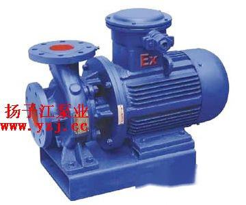
1. Product Overview of ISWB Type Horizontal Single-Stage Explosion-Proof Pipeline Centrifugal Pump:
The ISWB type horizontal single-stage explosion-proof pipeline centrifugal pump is designed and manufactured based on advanced domestic and international technologies, featuring a unique structural combination design. It is strictly manufactured in accordance with the international standards and the new national pipeline centrifugal pump standard JB/T53058-93, making it an efficient and energy-saving product. The ISW type horizontal centrifugal pump adopts advanced domestic hydraulic model optimization design. Additionally, based on different operating temperatures and media, it has derived thermal water pumps, high-temperature pumps, chemical pumps, and oil pumps, making it a currently standardized and promoted product by national standards.
A centrifugal pump is generally driven by an electric motor. Before starting the pump, the pump body and the suction pipeline are filled with liquid. When the impeller rotates at high speed, it drives the liquid between the blades to rotate as well. Due to the action of centrifugal force, the liquid is thrown from the center of the impeller to the outer edge (flow velocity can increase to 15-25 m/s), and its kinetic energy increases correspondingly. When the liquid enters the pump casing, the flow path in the volute casing gradually expands, causing the flow velocity to decrease and part of the kinetic energy to be converted into static pressure energy, allowing the liquid to flow out at a higher pressure along the discharge outlet. At the same time, a certain vacuum is formed at the center of the impeller due to the liquid being thrown out, resulting in the pressure at the liquid level (Pa) being higher than that at the center of the impeller. Consequently, the liquid in the suction pipeline is drawn into the pump due to the pressure difference. The impeller continues to rotate, and the liquid is continuously sucked in and expelled. The ability of the centrifugal pump to transport liquid relies mainly on the action of centrifugal force, hence the name centrifugal pump.
Centrifugal pumps are widely used in chemical production due to their outstanding advantages, including a wide range of performance applicability (covering flow, head, and adaptability to media properties), compact size, simple structure, ease of operation, uniform flow, low failure rates, long service life, and relatively low purchase and operating costs. Therefore, this chapter will focus on discussing centrifugal pumps as a typical example of the application of fluid mechanics principles.
1. Discussion of the Basic Structure and Working Principle of the Centrifugal Pump
(a) Basic Structure of the Centrifugal Pump
The basic components of a centrifugal pump are the high-speed rotating impeller and the fixed volute casing. The impeller, which has several (usually 4-12) backward curved blades, is secured to the pump shaft and rotates at high speed driven by the motor. The impeller is the component that directly does work on the liquid inside the pump and serves as the energy supply device for the centrifugal pump. The suction inlet in the center of the pump casing is connected to the suction pipeline, and the discharge outlet on the side of the pump casing is connected to the discharge pipeline equipped with a regulating valve.
(b) Working Principle of the Centrifugal Pump
When the centrifugal pump is started, the pump shaft drives the impeller to rotate at high speed, forcing the liquid pre-filled between the blades to rotate as well. Under the action of inertial centrifugal force, the liquid moves radially from the center of the impeller outward. During the process of the liquid flowing through the impeller, it gains energy, increasing its static pressure energy and flow velocity. When the liquid leaves the impeller and enters the pump casing, it slows down due to the gradually expanding flow path inside the casing, and part of the kinetic energy is converted into static pressure energy, which then flows tangentially into the discharge pipeline. Therefore, the volute casing not only collects the liquid that exits the impeller but also serves as an energy conversion device. As the liquid is thrown from the center of the impeller toward the outer perimeter, a low-pressure zone forms at the center of the impeller, causing the liquid to be drawn into the center of the impeller due to the potential energy difference between the liquid surface and the center of the impeller. With the continuous rotation of the impeller, the liquid is continuously sucked in and expelled. The mechanical energy obtained by the liquid in the centrifugal pump ultimately manifests as an increase in static pressure energy.
It should be emphasized that if the pump casing is not filled with the liquid to be transported before starting the centrifugal pump, the centrifugal force generated after the impeller's rotation is insufficient to create a low pressure in the impeller's center to draw liquid from the suction tank. Therefore, even if the centrifugal pump is started, it cannot transport liquid. This indicates that centrifugal pumps lack self-priming capability; this phenomenon is referred to as air binding. The installation of a one-way bottom valve in the suction pipeline is to prevent the liquid that has been filled in the pump casing from flowing back out before starting. Air entering the pump casing from the suction pipeline will also cause air binding.
(c) Impeller and Other Components of the Centrifugal Pump
1. Impeller of the Centrifugal Pump
The impeller is the key component of the centrifugal pump.
(1) Depending on its mechanical structure, impellers can be classified into closed, semi-closed, and open types. Closed impellers are suitable for transporting clean liquids; semi-closed and open impellers are suitable for transporting suspensions that contain solid particles, but these types of pumps have lower efficiency. In operation, part of the high-pressure liquid leaving the impeller can leak into the cavity between the impeller and the pump casing, causing a pressure difference where the liquid pressure at the impeller front-side suction inlet is lower. This results in an axial thrust directed toward the impeller's suction inlet side. This force pushes the impeller toward the suction inlet side, causing wear at the contact point between the impeller and pump casing, which can lead to vibration and disrupt normal pump operation. Drilling several small holes in the impeller back cover can reduce the pressure difference across the impeller, thereby mitigating the adverse effects of the axial thrust, although this also reduces the pump's efficiency. These small holes are called balance holes.
(2) According to the method of liquid suction, impellers can be classified into single-suction and double-suction types. Single-suction impellers have a simple structure and can only suck liquid from one side. Double-suction impellers can symmetrically suck liquid from both sides, which not only increases the suction capacity but also virtually eliminates axial thrust.
(3) Based on the geometric shape of the blades on the impeller, blades can be classified into backward curved, radial, and forward curved types. Backward curved blades are widely used as they facilitate the conversion of liquid kinetic energy into static pressure energy.
2. Guide Wheel of the Centrifugal Pump
To reduce energy losses caused by the liquid leaving the impeller directly entering the pump casing due to impact, a fixed guide wheel with blades is sometimes installed between the impeller and the pump casing. The blades in the guide wheel gradually redirect the liquid entering the pump casing while continuously expanding the flow path, allowing part of the kinetic energy to be effectively converted into static pressure energy. Multi-stage centrifugal pumps generally install guide wheels. The volute casing, backward curved blades on the impeller, and guide wheels all enhance the energy conversion rate from kinetic to static pressure, and thus can be considered energy conversion devices.
3. Shaft Sealing Device
Due to the rotation of the pump shaft while the pump casing remains stationary, there must be a certain gap at the contact point between the shaft and the pump casing. To prevent high-pressure liquid inside the pump from leaking out through this gap or to prevent external air from entering the pump from the opposite direction, a shaft sealing device must be installed. The shaft sealing devices in centrifugal pumps include packing and mechanical (face) seals. Packing consists of a sealing ring made of soft packing (such as oil-soaked or graphite-coated asbestos rope) around the gap where the pump shaft passes through the pump casing. Mechanical seals consist of a dynamic ring mounted on the rotating shaft and a static ring fixed to the pump casing. The end faces of the two rings are pressed together by spring force and rotate relative to each other, serving the sealing function. Mechanical seals are suitable for high-sealing applications, such as transporting acidic, alkaline, flammable, explosive, and toxic liquids. When the centrifugal pump starts, the pump shaft drives the impeller to rotate at high speed, forcing the liquid pre-filled between the blades to rotate, and under the action of inertial centrifugal force, the liquid moves radially from the center of the impeller outward. The liquid gains energy during its movement through the impeller, increasing its static pressure energy and flow velocity. When the liquid leaves the impeller and enters the centrifugal pump casing, the flow path within the casing gradually expands, causing the liquid to slow down, and part of its kinetic energy is converted into static pressure energy, flowing tangentially into the discharge pipeline. Thus, the volute casing not only collects the liquid thrown out by the impeller but also acts as an energy conversion device. As the liquid is thrown from the center of the impeller to the outer perimeter, a low-pressure zone forms at the center of the impeller, causing the liquid to be drawn into the impeller's center due to the potential energy difference between the liquid surface and the impeller center. With continuous rotation of the impeller, the liquid is continuously sucked in and expelled. The mechanical energy obtained by the liquid in the centrifugal pump ultimately manifests as an increase in static pressure energy. The role of the impeller is to directly transfer the mechanical energy of the prime mover to the liquid to increase the static and dynamic energy of the liquid (primarily increasing static energy).
1. Impeller
The impeller's role is to directly transfer the mechanical energy of the prime mover to the liquid to increase the static and dynamic energy of the liquid (primarily increasing static energy). Impellers can be open, semi-closed, or closed. Open impellers have no cover plates on both sides of the blades, are simple to manufacture, easy to clean, and are suitable for transporting materials with a considerable amount of suspended solids, but their efficiency is low, and the pressure of the liquid transported is not high; semi-closed impellers have no cover plate on one side of the suction inlet but have a cover plate on the other side, suitable for transporting materials that tend to settle or contain particles, also with lower efficiency; closed impellers have cover plates on both sides of the blades, have high efficiency, and are suitable for transporting clean liquids without impurities.
Most centrifugal pump impellers fall into this category.
2. Pump Casing
The function of the pump casing is to enclose the impeller in a certain space, allowing liquid to be sucked in and expelled by the impeller's action. The centrifugal pump casing is often made in a volute shape, hence also referred to as a volute. Due to the gradually expanding cross-sectional area of the flow path, the high-speed liquid thrown out from the impeller gradually reduces its flow velocity, facilitating the effective conversion of part of its kinetic energy into static pressure energy. The pump casing not only collects the liquid thrown out by the impeller but also acts as an energy conversion device.
The Concept of Centrifugal Force
Centrifugal force is essentially a manifestation of an object's inertia. For example, when a raindrop on an umbrella spins slowly with the umbrella, it follows the umbrella due to the frictional force acting as centripetal force. However, if the umbrella spins faster, this frictional force may not be sufficient to keep the raindrop moving in a circular path, causing it to fly outward. This is similar to a stone being swung in a circle by a string; if the speed is too high, the string will break, and the stone will fly out. This is what is meant by centrifugal force. The centrifugal pump is designed based on this principle. The high-speed rotating blades of the impeller drive the water to spin, throwing the water out and thus achieving the pumping purpose. There are many types of centrifugal pumps. They can be classified into domestic and industrial pumps based on usage, and into clean water pumps, impurity pumps, and corrosion-resistant pumps based on the media being transported. The basic structure of a centrifugal pump consists of six parts: impeller, pump body, pump shaft, bearings, sealing ring, and packing.
1. The impeller is the core part of the centrifugal pump, with high speed and great output power. The blades on the impeller play a crucial role, and the impeller must undergo static balance testing before assembly. The inner and outer surfaces of the impeller are required to be smooth to reduce friction loss in the water flow.
2. The pump body, also known as the pump casing, is the main body of the pump. It supports and fixes the structure and connects to the bracket where the bearings are installed.
3. The function of the pump shaft is to connect to the electric motor through a coupling and transmit the motor's torque to the impeller, making it the main component for transferring mechanical energy.
4. Bearings are components that support the pump shaft and come in two types: rolling bearings and sliding bearings. Rolling bearings use grease as lubricant and should be filled to about 2/3 to 3/4 of their capacity; too much can cause overheating, while too little may result in noise and heating! The sliding bearings used in centrifugal pumps are lubricated with transparent oil, which should be filled to the oil level line. Excess oil will seep along the pump shaft and cause splashing, while too little will cause the bearings to overheat and burn out, leading to accidents! During pump operation, the temperature of the bearings can reach as high as 85 degrees, typically running around 60 degrees; if it exceeds this, the cause should be investigated (e.g., whether there are impurities, whether the oil is blackened, or whether water has entered) and addressed promptly!
5. The sealing ring, also known as the leakage reduction ring, is installed to prevent high-pressure water in the pump from flowing to the low-pressure area through excessive gaps between the impeller inlet and the pump casing, which could affect the pump's water output and reduce efficiency. A gap that is too small could cause friction between the impeller and pump casing, leading to wear. To increase backflow resistance and reduce internal leakage, sealing rings are installed at the junction of the pump casing's inner edge and the impeller's outer edge, with a recommended gap of between 0.25 to 1.10 mm.
6. The packing consists of packing, water seal rings, packing barrels, packing nuts, and water seal pipes. The primary function of the packing is to seal the gap between the pump casing and the pump shaft to prevent the water from flowing out and external air from entering the pump, thereby maintaining vacuum inside the pump! When friction between the pump shaft and packing generates heat, water from the water seal pipe cools the packing! This ensures the normal operation of the pump. Therefore, special attention should be paid to checking the packing during operational inspections of the pump. Packing should be replaced approximately every 600 hours of operation.
2. Applications of ISWB Type Horizontal Single-Stage Explosion-Proof Pipeline Centrifugal Pump:
1. The ISWB type horizontal single-stage explosion-proof pipeline centrifugal pump is used for transporting clean water and other liquids with physical and chemical properties similar to clean water. It is suitable for industrial and urban water supply and drainage, high-rise building water pressure boosting, garden irrigation, fire-fighting pressure boosting, long-distance transportation, HVAC circulation, and cold and hot water circulation in bathrooms, with a usage temperature T ≤ 80℃.
2. The ISWR horizontal hot water pump is widely used in metallurgy, chemical, textile, paper-making, as well as in boilers for hot water pressure boosting and urban heating systems, with a usage temperature T ≤ 120℃.
3. The lSWH horizontal chemical centrifugal pump is used for transporting liquids that do not contain solid particles, are corrosive, and have a viscosity similar to water, applicable in petroleum, chemical, metallurgy, electric power, paper-making, food, pharmaceuticals, and synthetic fibers industries, with a usage temperature of -20~C to +120℃.
4. The lSWB horizontal pipeline oil pump is used for transporting petroleum products such as gasoline, kerosene, diesel, or other flammable and explosive liquids, with a temperature range for the transported medium from -20~C to +120℃.
3. Working Conditions of ISWB Type Horizontal Single-Stage Explosion-Proof Pipeline Centrifugal Pump:
1. Suction pressure ≤ 1.6MPa, or the maximum working pressure of the pump system ≤ 1.6MPa, that is, pump suction inlet pressure + pump lift ≤ 1.6MPa, and the static pressure test pressure of the pump is 2.5MPa. Please specify the system operating pressure when placing an order. If the working pressure of the ISWB type horizontal single-stage explosion-proof pipeline centrifugal pump system exceeds 1.6MPa, please indicate this when ordering, so that the hydraulic components and connection parts of the pump can be manufactured using cast steel materials.
2. Ambient temperature < 40℃, relative humidity < 95%.
3. The volume content of solid particles in the transported medium does not exceed 0.1% per unit volume, and the particle size is < 0.2mm.
Note: If the medium contains fine particles, please specify this when ordering so that the manufacturer can use wear-resistant mechanical seals.
4. Product Features of ISWB Type Horizontal Single-Stage Explosion-Proof Pipeline Centrifugal Pump:
Smooth Operation: The concentricity of the pump shaft and the excellent dynamic-static balance of the impeller ensure stable operation with no vibration.
Leak-Free: Seals made from different materials of hard alloys ensure no leakage when transporting various media.
Low Noise: The pump operates smoothly under support from two low-noise bearings, with minimal noise apart from the slight sound of the motor.
Low Failure Rate: With a simple and reasonable structure, and key components using international quality standards; the overall fault-free operating time of the machine is significantly increased.
Easy Maintenance: Sealing and bearing replacements are simple and convenient.
Space-Saving: The outlet can be directed to the left, right, or upward, facilitating pipeline layout and installation, thus saving space.
5. Model Significance of ISWB Type Horizontal Single-Stage Explosion-Proof Pipeline Centrifugal Pump:
For example: ISW100-160(I)AB
ISW - Horizontal Centrifugal Pump
100 - Pump inlet and outlet diameter (mm)
160 - Nominal diameter of the impeller (mm)
I - Flow classification
AB - Impeller diameter, secondary cutting