


Optimizing the economic benefits of extruders: An Analysis of Factors Affecting Production Efficiency
The co-rotating twin-screw extruder (hereinafter referred to as the extruder) has become the most essential equipment in modified plastic processing due to its excellent blending performance, customizable screw configuration, and good self-cleaning properties.
Extruder capacity efficiency is a parameter highly valued by modification companies when selecting equipment. It is generally believed that extruders with larger diameters have greater capacity efficiency.In fact, a large diameter is not the only factor in improving the capacity efficiency of an extruder. Factors affecting the capacity efficiency of an extruder include the extruder speed, volumetric efficiency, specific torque, screw configuration design, material formulation state, plasticization condition, and equipment wear.
Below, we will analyze the influencing factors one by one according to the state of the material in different processes in the extruder and the screw combination design. In this article, we will start fromExtrusion conveying mechanismFrom the perspective of expanding in detail.
Extrusion conveying mechanism
The study of the conveying mechanism of single-screw extruders is the foundation for the development of twin-screw extruders. The earliest single-screw conveying theory was proposed by Darnel and Mol, whose core viewpoint is that the driving force for material transport in single-screw extruders is based on frictional drag for solid conveying. As the lead of the extruder screw elements gradually decreases or the kneading resistance elements exert pressure, the initially loose and dispersed material transforms into a solid plug with no relative displacement. Under the combined action of the friction between the solid plug and the screw surface and the friction between the solid plug and the inner surface of the barrel, the solid plug is transported forward along the screw channel.
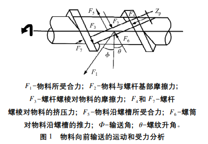
The classical conveying theory, when proposed, had its limitations. It assumes that there is no relative displacement within the solid plug and that the frictional force it experiences is constant. However, the actual situation is quite different, often leading to significant discrepancies between the theoretical calculation formulas and reality. Despite this, the theory elucidates the essence of screw conveyor extrusion, that is, the frictional component force of the barrel on the material along the screw groove and screw thread is the driving force for material conveyance, while the frictional force between the rotating screw surface and the material serves as the resistance restricting the material's forward movement. In other words, the difference between the friction coefficient \( f_i \) of the conveyed material with the screw metal surface and the friction coefficient \( f_b \) of the material with the inner metal surface of the barrel is the source of the friction drag conveying driving force. The movement and force analysis of the material being conveyed is shown in Figure 1.
Although the earliest and most detailed theory of solid conveying based on the statics of solid friction was proposed by Darnel and Mol, it includes several fundamental assumptions:
In the screw channel of the extruder, the resin material exists in a solid plug state. Additionally, it has a fixed conveying rate, and the pressure direction endured by the solid plug in the extruder is consistent only with the material movement direction.
The solid plug and any surface within the screw groove interact with each other, and their coefficient of friction does not vary with pressure fluctuations but changes with temperature variations.
Ignoring the changes in the volumetric density of the solid plug and the influence of Earth's gravity, and assuming that there is no gap between the extruder barrel and screw.
The screw is stationary relative to the barrel, considering the barrel to be in motion.
Potente et al. believe that in the axial screw grooves, the bulk density/packing density of materials differs in various regions. In some regions, the material is in a loose state, while in others, the material is under pressure, forming a solid plug. The conveying mechanism of the solid plug portion is consistent with the Darnell-Mol conveying theory. Through the analysis of the motion state and the forces on the solid plug, the following formula is derived:
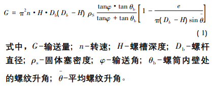
From formula (1), it can be seen that the throughput G is positively correlated with the speed n, volumetric efficiency H, and screw diameter Db. Since the assumptions of the Darnel and Mol single-screw conveying theory do not align with reality, the calculated data results from their theoretical formulae have significant deviations from actual production data. Subsequently, many scholars have conducted more detailed research based on this theory. Among the numerous studies, two theories proposed by Chung and others have been widely accepted by many scholars.Viscous Traction Theory of Molten Film Traction Material on the Inner Wall of the Screw TubeProposed by TedderEnergy balance theory。
Despite the debates among various theories, the fundamental starting point of both the Darnell-Mol theory and the Tedder theory is the same: the dynamic friction between the material in the single-screw extruder and the inner wall of the screw barrel is the essential driving force for solid material conveying. The difference is that Chung believes the material first forms a melt film through friction with the metal wall of the barrel, and it is this viscous drag force generated by the melt film that affects the performance of solid conveying.The commonality among the aforementioned three theories is that they all assume the solid material in the extruder to be a solid plug, meaning that the material in the solid conveying section is considered to be dense, with no relative displacement between the internal solid particles.
Zhu Fuhua and others observed during the fully visualized operation of an extruder that before the material enters the melting zone, the solid particles are primarily in a mutual sliding exchange process, and the screw grooves are not completely filled. This phenomenon gradually disappears only after entering the melting zone. Additionally, as the resin particles are conveyed forward, bright shiny melt can be clearly observed between the resin particles. As the material progresses to the rear section, the space occupied by the melt increases, and the boundary between the particles and the melt becomes less distinct. This visually demonstrates the discontinuity of the solid plug and the inevitability of changes in solid plug displacement. Based on extensive observational experiments, Zhu Fuhua and colleagues were the first to propose the theory of non-plug flow solid conveying.
Regrettably, for a long time after the non-plug flow solid transport theory was proposed, it could not be adopted domestically or internationally to address practical problems due to its complexity. Although the computational accuracy of the non-plug flow solid transport theory has significantly improved, there are no explicit formulas for calculating yield and pressure. Additionally, it is inherently a nonlinear contact problem with numerous and complex formulas, requiring the use of the finite element method for calculations, which poses significant challenges for practical applications.
Carrot and others studied the geometry of intermeshing contracts for twin-screw systems and, based on their research, created a model of the material conveying process in a twin-screw extruder. They unanimously suggested that the conveying process of materials in the extruder is complex and diverse, with two main conveying mechanisms: positive displacement conveying along the screw axis in the intermeshing zone and frictional drag conveying in the screw channel. Liu Tinghua and others conducted extensive experiments using a fully three-directional visual extruder, dividing the solid conveying section into positive displacement conveying in the intermeshing zone and granular friction conveying in the side screw channel. The calculation of the positive displacement conveying capacity in the intermeshing zone is shown in formula (2).
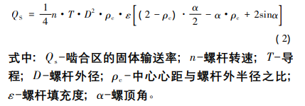
From Equation (2), it can be seen that the solid conveying capacity in the meshing zone is only related to the screw geometry parameters, rotational speed n, and fill factor ε.
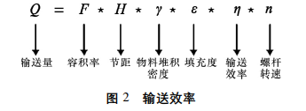
Neither the classical single-screw conveying theory nor the twin-screw conveying theory can precisely calculate the exact process parameters of a screw extruder. However, they both reveal the essence of conveying efficiency, which is comprehensively influenced by factors such as the screw's volumetric efficiency, pitch (lead), material bulk density, dynamic friction coefficient, screw speed, and material fill level, as shown in Figure 2. Therefore, we can only qualitatively analyze the specific situation. In practical applications, the factors affecting conveying efficiency may be one or several. At this point, we need to combine practical experience with theoretical knowledge to identify the primary contradictions and solve the main problems.
The maximization of the economic benefits of an extruder is inseparable from the production efficiency of the extruder.The production capacity efficiency is not only determined by the physical parameters of the extruder and process conditions, but also influenced by the material state. The lower the bulk density of the material, the higher the air content within the material. For the process of screw conveying the material, it is essentially about moving the material forward within the same volume. A decrease in bulk density thus implies a reduction in conveying capacity.
During the melt blending in an extruder, a large number of particles and powders are compressed and transformed into a melt, releasing the remaining trapped air. The only way for this air to exit the interior of the extruder is to flow backward toward the tail of the extruder. The reverse flow of air prevents the continued feeding of the powder. When the reverse flow pressure/speed exceeds a certain critical value, it results in the backflow of the powder. As the cross-sectional free area of the screw becomes smaller or the material filling rate approaches 100%, the reverse flow speed/pressure of the air becomes greater. At this point, increasing the rotational speed may actually have a negative impact on the feeding rate because the overflow point of the rate decreases with the increase in speed, meaning that the higher the rotational speed, the more the feeding becomes fluidized. As previously mentioned, friction is the key factor affecting material conveying, and the conveying efficiency is proportional to the "dynamic" friction coefficient. The higher the friction coefficient of the barrel, the higher the conveying efficiency. Changes in the friction with the barrel during the melt mixing process in the extruder will also affect its conveying efficiency. Additionally, different screw combinations and structures will also affect its "dynamic" friction coefficient.
The following will analyze the influencing factors based on the state of the material during different processes in the extruder and the screw combination design.
Extrusion melting process
The melting process and theory may seem unrelated to the extrusion capacity efficiency, but they are actually interconnected. In the actual extrusion processing technology, material formulations with low capacity efficiency often consist of a combination of resin and powder. The powder itself lacks fluidity, and only when it is fully mixed into the molten resin can the screw barrel effectively push the material forward for extrusion. If the process settings are not appropriate, preventing the resin from fully plasticizing and melting, this can lead to the agglomeration of the non-fluid powder, which may block the extruder.
For formulations involving resin and powder, most process conditions choose a design where the resin is fed through the main feeder and the powder through the side feeder. This means that the resin and a portion of the powder are first introduced through the main feeding port of the first barrel section, melted and plasticized over 2-3 barrel lengths, and then the remaining powder is added using a side feeder at the downstream section of the extruder. If the resin fed through the main feeder is not fully plasticized and remains in a granular solid state, the powder added downstream cannot be properly entrained by the resin melt, which may restrict the feeding of the powder and affect production efficiency.
In addition, if the material is over-plasticized in the plasticizing section, the resin melt viscosity will drop sharply. Some resin melts will have excessively low strength and viscosity, making them unable to adhere to the powder. At the same time, the overall friction coefficient of the material decreases, directly affecting the conveying efficiency.
The melting of polymer solid particles, including solid granules, powders, beads, or flakes, is the most crucial fundamental phase in polymer processing. During this phase, the precisely metered feed material transitions from a solid state at room temperature to a melt state suitable for mixing and processing. The energy source for this transition mainly comes from external heating of the barrel and shear friction heat generated inside the screw. In fact, the heat provided by the external heating of the barrel accounts for only 30% of the melting energy, while 70% or even more of the melting energy comes from the shear friction heat generated by the rotation of the screw.
The plastic melting process begins with the material fed from the feed section being axially advanced by the screw. As the material contacts the heated metal inner wall of the extruder, melting commences. The melting process initially forms a layer of molten film at the interface between the material and the metal barrel, which continues to thicken. If the thickness of the molten film exceeds the gap between the screw flights and the barrel, it will be scraped off by the rotating screw flights and accumulate at the front side of the flights, forming a vortex-like molten pool. The rear side of the flights is occupied by a solid bed, also known as a solid plug, as illustrated in the melting model below. With the rotation of the screw, the molten film begins to flow along the surface of the screw.
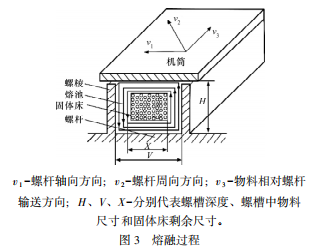
Meanwhile, the melt film also begins to appear at the inner wall of the barrel in the screw groove area and at the position between the two screws in the meshing area. The appearance of the melt film on the barrel's inner wall is due to the melting of the material caused by the constant heat flux density heating of the barrel wall. The melt film appearing in the meshing area mainly originates from the viscous dissipation heat generated in the narrow gap between the two screws. The melted polymer melt continues to flow under the rotation of the screws, first flowing across the surface of the screw flights, then flowing back along the inner wall of the barrel, forming a circulating flow within the screw groove.
During the melting process, as the screw volume rate gradually decreases, the solid material closely adheres to the inner wall of the screw barrel. Under the influence of external heating of the barrel and shear heat, as the material moves forward along the screw channel, the unmelted material in the solid bed will become less and less, and the melt pool gradually increases until all solid resin particles are completely melted and disappear, achieving complete melting. The melting and plasticizing process of the material occurs only at the interface between the melt film and the solid bed. The axial length from the formation of the melt film to the disappearance of the resin particles in the solid bed is referred to as the melting zone length, or the melting section.
From the above melting model, it can be observed that in the entire feeding and plasticizing section of the extruder, there are inconsistently compacted solid resins in the feeding section. In the melting section, the melt begins to form and grow, and there is a certain interface between the solid resin and the molten material until the solid material is completely melted and plasticized. It can be said that the entire melting process of the solid resin is mainly completed in the melting zone of the screw. Additionally, we can deduce the pattern of changes in the size of the solid bed along the axial direction of the screw during the plasticizing and melting process, providing an important basis for mathematical analysis. Obviously, if the rate of increase in the proportion of the melt pool space is lower than the rate of decrease in the screw channel depth, a blockage of the solid bed in the screw may occur, causing intermittent fluctuations in the extrusion flow. Therefore, the screw combination design is particularly crucial at this stage.
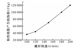
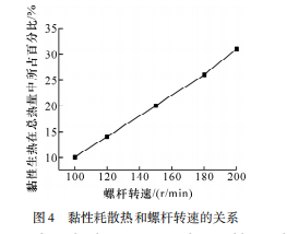
Liang Chang also studied the effect of screw speed on viscous dissipation heating. The figure below shows the effect of increased screw speed on viscous dissipation heating. It can be seen that as the screw speed increases, viscous dissipation heating also increases significantly. When the screw speed increases from 100 r/min to 200 r/min, the viscous dissipation heating increases nearly threefold. At the same time, the percentage of viscous dissipation heating in the heat supply during the melting process also shows a linear increase. When the screw speed doubles, the percentage of viscous dissipation in the system's heat increases from 10% to 30%. It is clearly visible from the figure below that as the screw speed increases, the percentage of viscous dissipation heating in the energy required for melting is linearly and sharply rising.
Screw combination and design
The screw combination design of a twin-screw extruder is crucial in the conveying and plasticizing process of the extruder. In conventional production extruders, considering economic and practical aspects, the length of the extruder is typically selected between 40D to 56D (D represents the nominal diameter of the screw). For machines with side feeding for powders, the plasticizing section is often set to a length of only 4D to 8D. To ensure that the resin is basically plasticized within such a short plasticizing length, some resistance kneading elements are added in the screw design, as shown in the figure. Although the addition of resistance elements can significantly increase the residence time and shear intensity of the material in the plasticizing section, thereby resulting in better plasticizing outcomes, these elements can also affect the conveyance of the main feeding material and increase the energy consumption of the extruder. Therefore, in actual screw process design, a comprehensive consideration is needed to ensure adequate plasticization of the material while avoiding excessive pressure in the extruder.
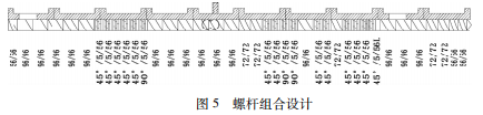
In the use of conveying screw elements, it is preferable to select screw elements with a lead of 1D to 2D. According to the theory of solid conveying, the material in the non-kneading zone is pushed forward by the screw barrel along the screw thread. The axial length of one complete rotation of the screw thread is the lead length of the screw element, meaning that screw elements with a larger lead have higher conveying efficiency. However, the lead of conveying screw elements should not be excessively large, as an overly large lead can result in excessive circumferential shear, which can hinder the forward conveying of materials.
Moreover, the "number of heads" in the screw elements has a significant impact on the material conveying efficiency. More heads mean more thrust surfaces for conveying, which can increase the material conveying rate. However, the resulting decrease in volumetric efficiency may actually limit the overall conveying efficiency. In critical conveying areas, single-head or double-head conveying elements are often chosen, and the use of multi-head elements should be avoided.
In the shear kneading functional elements, it is advisable to choose forward shear elements with smaller kneading disc angles as much as possible. In certain screw functional areas, if large-angle or reverse shear elements have to be used to improve plasticizing and dispersing efficiency, they should be placed away from the feed inlet. Compared to traditional shear kneading elements, extensional flow elements have better results in plasticizing efficiency and dispersing mixing, and they do not introduce excessive conveying resistance when improving plasticizing and mixing effects, thereby enhancing extrusion productivity.
The essence of extruder conveying is the friction of the barrel on the material along the extrusion direction of the screw and the forward conveying in the screw engagement area. Factors affecting the conveying efficiency of the extruder includeThe geometric parameters of the equipment, the state of the formulation materials, the control of the melting process, and the combination and design of the screws.。
The melting process, although occurring after the feeding section of the extruder,If the melting efficiency is inadequate or too high, it will affect the capacity efficiency.The essence of the melting process is the formation of the melt film and the growth of the melt pool, with the primary source of melting energy being the heat generated by friction in the extruder and viscous dissipation.
The screw combination and design are key factors affecting the efficiency of extrusion conveying.By selecting different screw element models, sizes, and structures, the optimal material conveying efficiency for different formulations can be achieved. A large lead can provide higher conveying efficiency, but an excessively large lead may result in higher circumferential shear, hindering material conveying. Although the use of resistance elements can improve the efficiency of material melting and plasticizing, it will reduce conveying efficiency. The specific combination design needs to be comprehensively considered in conjunction with the specific formulation composition.
【Copyright and Disclaimer】The above information is collected and organized by PlastMatch. The copyright belongs to the original author. This article is reprinted for the purpose of providing more information, and it does not imply that PlastMatch endorses the views expressed in the article or guarantees its accuracy. If there are any errors in the source attribution or if your legitimate rights have been infringed, please contact us, and we will promptly correct or remove the content. If other media, websites, or individuals use the aforementioned content, they must clearly indicate the original source and origin of the work and assume legal responsibility on their own.
Most Popular
-

AI Computing Power Demand Ignites Electronic Fabrics! China Jushi Hits Limit Up! Domestic Substitution Welcomes Golden Window
-

Focus on going global! kingfa sci. leads, huitong, preter, and kumho nire follow, china’s modified plastics frenziedly expanding worldwide
-

PA66 Cost and Profit: Broad-Based Weakness in the Feedstock Market Continues to Erode Cost Support for PA66 (202606)
-

Back-to-back major joker moves! covestro’s 1.32 million ton mdi dual-line expansion and hdi acquisition reshape global polyurethane landscape
-

Evonik Parts Ways With The Polyester Business! A Strategic Retreat By A Germany Chemical Giant And The Global Industry Shift