


Mastering Screw Configuration and Pressure Management Strategies to Unlock the Secrets of "Efficiency and Cost Reduction"
In the field of modified plastic processing, twin-screw extruders often suffer from limited production capacity and severe wear on components due to improper design and configuration, ultimately eroding the profitability of the process. To boost production while protecting core components, precise configuration must be carried out from three dimensions: the combination logic of screw elements, vent management, and pressure control.
The "Golden Lead" in the Feeding Zone: Ensuring Smoother Throughput
The efficiency of the feeding zone directly determines the total output of the extruder. To achieve the highest free volume capacity, a large-pitch conveying element should be prioritized at the first barrel section below the feed opening.
The subsequent pitch design should follow the principle of stepwise reduction: starting from a lead of 1.5-2D below the feed hopper, gradually decreasing to 1.5D or 1.25D, and stabilizing at 1D before entering the melting zone. This design effectively prevents abnormal wear of the material in the feeding area due to the repeated jumping of the pitch. Additionally, introducing diameter-reduced elements can increase the clearance between the screw flight and the barrel wall, gently reducing pressure peaks, thereby extending the equipment's lifespan.
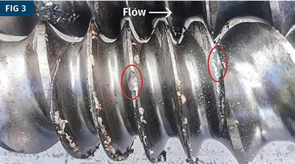
A real photo of the feed section of the screw. Here, the screw flight pitch changes from normal to a short pitch and then returns to normal. The red circle in the image highlights severe wear and pitting caused by this improper configuration.
Targeted component selection: Balancing self-cleaning and large volume
Although Erdmenger self-cleaning elements are the standard configuration for most operating conditions, non-wiping undercut elements can prove exceptionally effective in specific scenarios.
When handling low bulk density, fluffy materials, the larger free volume of the undercut element significantly increases the feed rate. In the vacuum venting section, the increased melt surface area provided by this element greatly enhances degassing efficiency.
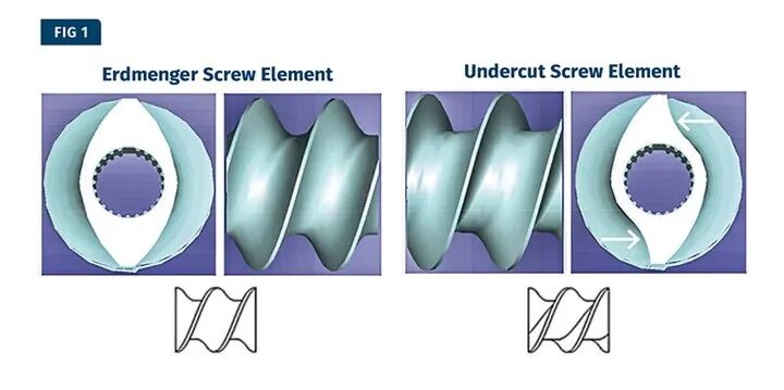
The figure shows a self-cleaning twin-screw conveying element (Erdmenger) and a thrust-face undercut conveying element (Undercut). The white arrows indicate the reduced-diameter structure at the thrust flanks. The rotation direction in the top view is clockwise. Source: KraussMaffei.
High-Filling Process: Overcoming the Challenge of Air “Rebound”
In high-fill processes where talc or calcium carbonate content exceeds 80%, the large amount of air introduced by the side feeder is the main cause of "overflow".
The axial openness of the exhaust channel is the core of solving the problem. It must be ensured that the mixing section between the exhaust ports is not fully filled, allowing air to flow smoothly out of the exhaust ports. If the mixing section is designed too tightly, forming a "melt seal," the air will not be able to move downstream and will be forced to flow back, carrying powder to the rear exhaust ports, leading to clogging of the exhaust ports or even leakage of material.
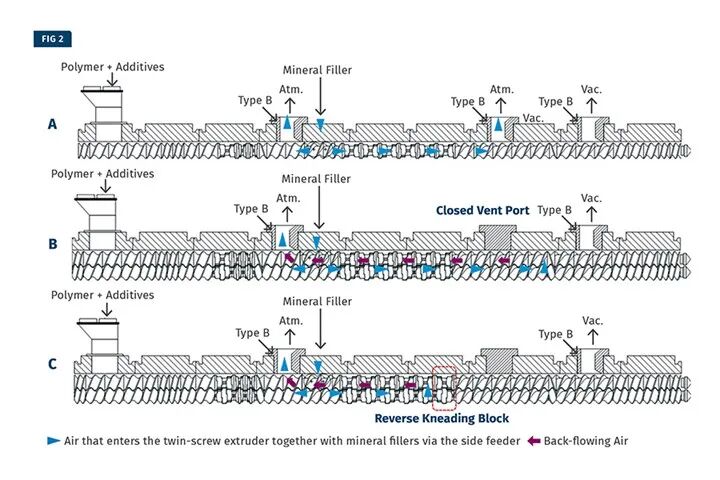
Schematic illustration of side-feeding extrusion process with low bulk density filler: A) Correct feeding method, maintaining clear pathways for both front and rear vent ports; B) Poor venting caused by blockage of the front atmospheric vent port; C) Incorrect design, where blockage of the front vent port or a reverse kneading block creates a "melt seal," preventing entrapped air from escaping through the front vent. Source: R. Segiet
Combination details: Avoid common "life shorteners"
Incorrect component layout is often the "silent killer" of the barrel and screw. For example, using wide kneading blocks at the start of the melting section can generate extremely high local pressure and wear, whereas narrow kneading blocks or triangular kneading blocks are better choices.
In addition, the positioning of the reverse element (water stop block) is also very particular. It is strictly prohibited to place it at the connection between two barrel sections, as this not only accelerates the wear of the two barrels but, in extreme cases, can also cause resin to seep out from the connection gaps. Fixing it within a single barrel can reduce maintenance costs by half.
Pressure Management: The Logic and Value of Introducing a Melt Pump
For high-viscosity materials or conditions requiring fine filter screens, the melt pump is not only a pressure-boosting tool but also a magic device for reducing consumption.
Typically, the inlet pressure of a melt pump is set at around 300 psi, which can significantly reduce the pressure at the extruder discharge—depending on the material and screen mesh, the pressure drop often reaches 1,500 psi or more. This pressure reduction directly translates into lower shear stress and better temperature control. Process data shows that for every 150 psi decrease in pressure, the melt temperature typically drops by 1–2°C. This not only protects heat-sensitive polymers but also effectively addresses leakage issues caused by localized high pressure.
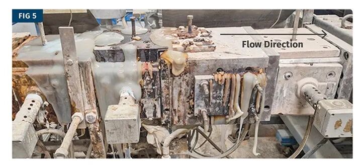
Excessively high head pressure caused melt leakage from multiple sealed barrel openings. Source: R. Segiet
Case: Why can't the filler be added from the main feed hopper?
In process design, the order of adding ingredients often determines the quality of the final product.
Taking the blending of HIPS (High Impact Polystyrene) and powdered chemical additives as an example: if both are added simultaneously to the main feed hopper, the additives will experience severe pre-agglomeration before melting. In a black resin matrix, the white powder will be tightly compressed between the screw thread tips and the barrel, forming hard agglomerates. This tight structure, formed before melting, is almost impossible to redisperse during the subsequent extrusion process, leading directly to product scrapping.
【Copyright and Disclaimer】The above information is collected and organized by PlastMatch. The copyright belongs to the original author. This article is reprinted for the purpose of providing more information, and it does not imply that PlastMatch endorses the views expressed in the article or guarantees its accuracy. If there are any errors in the source attribution or if your legitimate rights have been infringed, please contact us, and we will promptly correct or remove the content. If other media, websites, or individuals use the aforementioned content, they must clearly indicate the original source and origin of the work and assume legal responsibility on their own.
Most Popular
-

Continental Plans to Begin Sale of ContiTech in Early 2026
-

$4 Billion! Medtronic Makes Another Acquisition
-

BASF Delivers First Batch of Innovative Cathode Materials for Semi-Solid-State Batteries to Weilan New Energy
-
Profit and Revenue Growth Struggle to Conceal Debt Repayment Pressure; Success of Kingfa Sci & Tech's High-End Strategy Yet to Be Seen
-

Why did a century-old european dental instrument giant relocate its manufacturing hub to china?