


Extruder installation and maintenance sop: Establishing Standardized Maintenance Management Is Important!
During the maintenance of twin-screw equipment, if there is no SOP or standard, rushing to assemble or disassemble will inevitably lead to missing steps and standards. Once something is missed, the screw thread components may become impossible to disassemble and can only be removed destructively before being reinstalled, resulting in double the effort for half the result.
Therefore, only by establishing standardized SOPs can work efficiency and equipment utilization be improved, and maintenance costs reduced.
How should standardized maintenance be performed?
Twin-screw installation and disassembly
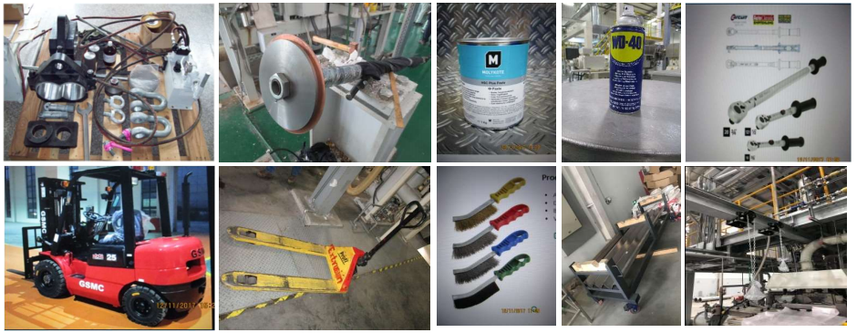
The materials needed for the installation and disassembly of the twin-screw extruder are as follows:
01
Screw installation
1. Distinguishing Screw Directions: The twin screws themselves do not have a distinction between left and right, but for the sake of training and standardization, we have deliberately assigned left and right directions to the screws.
Standing behind the main motor facing the barrel, the left hand side is the left of the equipment, and the right hand side is the right of the equipment. It is best to use a marker or an engraving pen to make a mark on the screw.
3. It is also best to use a marker to extend the direction to the threaded area at the screw connection, to facilitate the installation of the screw, as shown in the image below:
4. Double screw assembly. Stand on the side of the screw sleeve and mark the screw with "L" and "R" using a marker.
When the direction of the left screw spline groove is at the 12 o'clock position, the right screw spline groove is at the 3 o'clock position. Assemble the twin screws in this orientation with the cooperation of three people.
Similarly, the chuck is also locked in this direction. The gearbox output shaft direction is also pre-adjusted to the position of the left 12 o'clock and right 3 o'clock directions.
It is recommended to install screw lifting fixtures (even for 60/62 machines). These fixtures consist of two semi-elliptical rings, and the fixed traction device at the head of the screw should also be installed. They should be pre-installed to ensure there is no positional deviation of the twin screws.
When inserting the screw into the barrel, pour silicone oil/oil (process additive) onto the surface of the screw to ensure that there is no dry friction between the lubricated screw and barrel during the initial stage of startup without material.
If it is a 90 machine and above, a hydraulic installation and removal tool for the screw can be used (the positioning pin on the barrel must be removed in advance).
After installing the screw, be sure to use a torque wrench to apply the torque according to the drawing requirements.
a. For screw heads that are tightened using a coupling sleeve, use wood or a steel pipe to support and fix them at the locking screw position on the coupling.
The screw head uses hydraulic locking, and the torque should be checked with a hydraulic locking tool before installation.
02
Disassembly of the screw
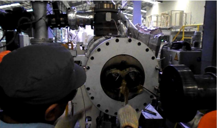
Before disassembling the twin screws, use cleaning material to clean the barrel, generally using PP or PE. If the customer has oil additives, oil can be used for cleaning.
2. Please remove the sensors in contact with the material.
After disassembling the material cylinder "8-0", it is best to use a copper spatula to clean the remaining material.
4. Use the tool for installing the screw rod and disassemble the screw rod in reverse order of installation. (Make sure to cut off the power, tag, and lock out before disassembling the screw rod.)
If you need to replace the screw block assembly, you can first loosen the screw head by half to one turn before removing the twin screws from the barrel, and then continue to loosen it (the connecting sleeve) in the maintenance room.
If the screw is difficult to clean, it needs to be placed in the barrel and heated before cleaning.
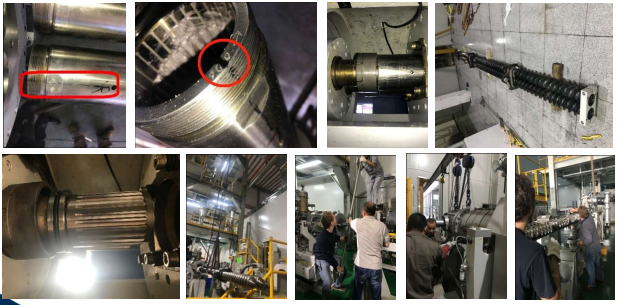
Extruder leveling and alignment
01
5 reference planes
Each gearbox has two reference surfaces at one corner: horizontal and vertical. However, not all gearboxes have these. If they are absent, the connecting end surface between the gearbox and the first barrel can be used as the reference surface.
Discharge port barrel inner surface process flow direction
The process flow direction of the inner surface of the exhaust port cylinder.
The direction of the surface process flow of the last section of the barrel.
The direction of the end face of the last barrel section
Check and adjust the base adjustment block (or the foot cup adjustment base). Generally, we require the equipment to be level at 0.1mm/m.
02
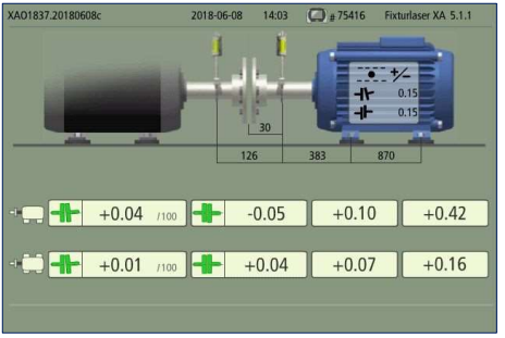
Alignment of gearbox and motor
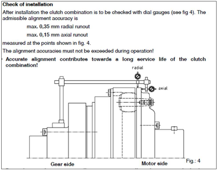
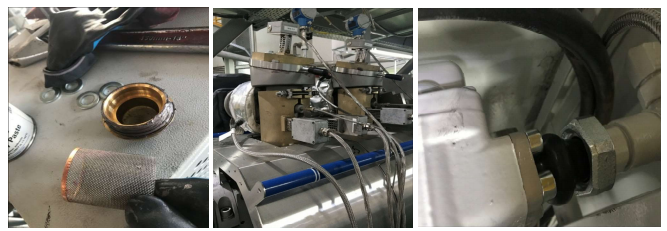
According to the manual, the pneumatic clutch requires compressed air for alignment.
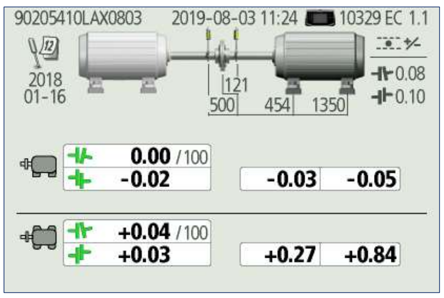
It is recommended that machines with 52 units or more use alignment instruments for alignment.
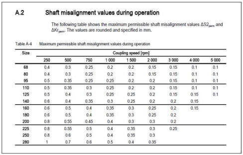
- For cold alignment and hot alignment, perform cold alignment before starting the machine, and after the equipment has been running for 24 hours, stop the machine for hot alignment.
First align left and right, then align up and down. Considering that the motor will have a compression change when finally tightened, try to let the motor rise slightly (about 0.02-0.04mm change), depending on the size of the equipment.
After alignment, use a marker to make marks on the adjustment positions of the screws on the motor base, which will be convenient for future inspection and preventive maintenance.
03
Align using an alignment instrument according to the centering requirements of the mechanical clutch.
04
Align using an alignment instrument according to the centering requirements of the pneumatic clutch.
Pre-start inspection items
01
Lubrication - Apply anti-seize agent MoS.2
All the fastening screws for connections, equipment, barrel, and die head connections.
- Exhaust port, vacuum port, lateral insertion port, plug
Gasket for the vacuum port, copper gasket for the exhaust port.
- Twin screw head, twin screw coupling sleeve
Y-type filter
02
Bolt tightening
After initially tightening all the barrel heating plates in a cold state, retighten them once the production operating temperature is reached.
The tightening of the die head, die, and barrel needs to follow the torque requirements in the manual, and should be done in steps and at different temperatures.
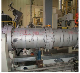
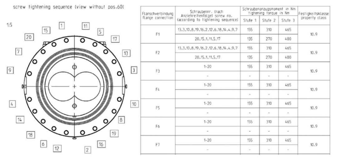
Key point: The tightening of the die head, the barrel, and the screw head must be done using a torque wrench!
In actual production processes, many extruder failures stem from inadequate and thorough daily maintenance. The key to daily maintenance is to establish standardized operating procedures and strictly adhere to these standards.
To ensure the normal operation of the extruder, it is most important to establish a standardized SOP to improve work efficiency and equipment utilization, thereby reducing downtime and lowering maintenance costs.
【Copyright and Disclaimer】The above information is collected and organized by PlastMatch. The copyright belongs to the original author. This article is reprinted for the purpose of providing more information, and it does not imply that PlastMatch endorses the views expressed in the article or guarantees its accuracy. If there are any errors in the source attribution or if your legitimate rights have been infringed, please contact us, and we will promptly correct or remove the content. If other media, websites, or individuals use the aforementioned content, they must clearly indicate the original source and origin of the work and assume legal responsibility on their own.
Most Popular
-

AI Computing Power Demand Ignites Electronic Fabrics! China Jushi Hits Limit Up! Domestic Substitution Welcomes Golden Window
-

Focus on going global! kingfa sci. leads, huitong, preter, and kumho nire follow, china’s modified plastics frenziedly expanding worldwide
-

Back-to-back major joker moves! covestro’s 1.32 million ton mdi dual-line expansion and hdi acquisition reshape global polyurethane landscape
-

Evonik Parts Ways With The Polyester Business! A Strategic Retreat By A Germany Chemical Giant And The Global Industry Shift
-

PA66 Cost and Profit: Broad-Based Weakness in the Feedstock Market Continues to Erode Cost Support for PA66 (202606)