


Barrel wear at extruder feed port significantly affects output! how to adjust?
The barrel and screw will wear over time, which leads to a decrease in extrusion output and an increase in discharge temperature. Generally, the screw wears faster than the barrel, with the lifespan of one barrel typically equivalent to that of three screws. When the screw wear becomes severe enough to reduce the economic efficiency of the process operation, the screw should be replaced.
Where does the inlet wear out the fastest?
The wear rates of the screw and barrel depend on the type of extruded resin, the solid content in the local channel, the content and type of filler in the resin, speed (screw rotation speed), local pressure, structural materials, and the fit between the barrel and the gearbox.The highest wear rate typically occurs at the end of the transition section, where solid particles may become trapped at the exit of the barrier section. At this location, the pressure may also be relatively high, and both the screw and the barrel may experience higher wear rates.
The feed barrel of a twin-screw extruder also experiences wear, but the wear rate is lower than that of the barrel. The wear rate of the housing depends on the local pressure and the fillers in the resin, with the lower wear rate attributed to the lower pressure inside the feed housing. The housing is usually made of malleable steel. To reduce the wear rate, the screw thread grooves can be cut to 2-3 times the normal thread clearance, and the barrel can be manufactured slightly larger.On older extruders, after several barrel replacements, wear of the feed section barrel may become severe enough to reduce the extruder’s output rate and cause fluctuations in throughput.
Case Analysis (Taking Single Screw as an Example)
For example, a 4.5-inch diameter extruder with a smooth inner bore experienced severe random motor current fluctuations when extruding polystyrene (PS) resin at a lower rate. The extruder's screw geometry is very standard and suitable for PS overflow feed plasticizing extrusion. The extruder operates at the maximum screw speed, which is the bottleneck step of the production line. A higher extrusion rate was expected, but it could not be achieved. The operating rate of the extruder is about 60% of the expected rate, meaning the actual rate is 60% of the expected rate.
The specific output rate is the output rate divided by the screw speed. Both the barrel and the screw are new, so their clearance specifications meet the standards for this size extruder. Figure 1 shows the motor current and output pressure, indicating unstable operation. The motor current fluctuates between 120 and 200 amperes, which is abnormal for a machine of this size and mode of operation. However, during this period, the output pressure of the production line remains relatively stable, producing high-quality products, albeit with an output rate far below expectations.
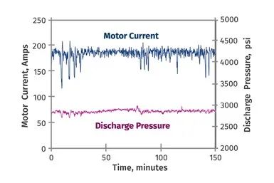
Figure 1 Changes of motor current and discharge pressure over time.
After an investigation, it was confirmed that the barrel had been replaced multiple times. The focus shifted to inspecting the wear condition of the feed barrel. Since the barrel had already been installed and aligned with the gearbox, it was decided to remove the screw and check whether there was a flange at the connection between the barrel and the feed barrel. An optical inspection mirror was inserted into the feed barrel below the hopper. The mirror revealed an annular flange at the connection between the feed barrel and the new barrel. The flange was approximately 2.5 millimeters wide. Therefore, the diameter of the feed barrel had worn by about 5 millimeters, forming a cylindrical section larger than the inner diameter of the new barrel.
It is currently unclear whether the axial wear is uniform. Figure 2 provides a schematic diagram of the flange. The wear debris has also caused the gap between the thread cutting edge and the housing to reach 2.6 millimeters, approximately 25 times the normal clearance. This gap is roughly equivalent to the size of a PS particle. Therefore, particles can pass through the thread cutting edge, although this may only be a minor issue.
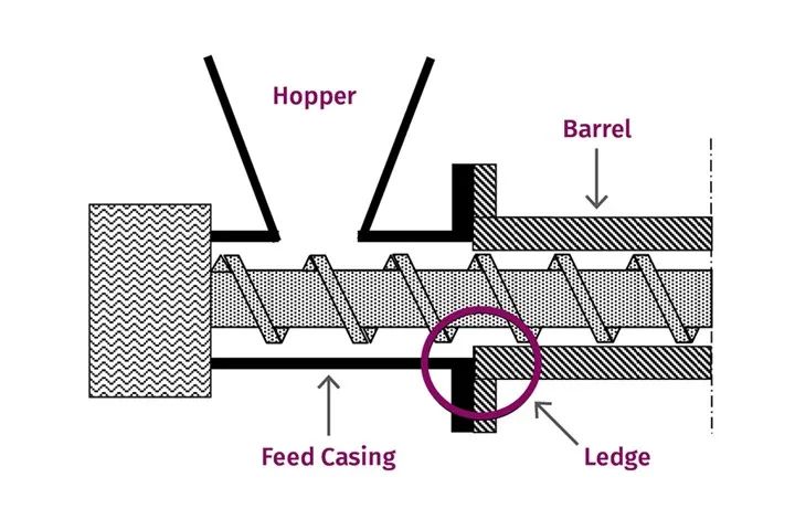
Figure 2 Schematic diagram of a worn cartridge case and a new barrel. A protrusion is formed at the flange connection.
The flange is sufficiently large to obstruct the conveyance of particles, thereby restricting the flow of solids from the feed sleeve to the barrel. When the restriction reaches its maximum, the extruder operates at a lower fill level, causing the motor current to drop sharply, as shown in Figure 1. When the particles begin to flow at a higher rate, the motor current returns to the baseline level. As mentioned earlier, the extruder is operating at only 60% of the expected speed. The production line fails to meet product demand.
Solution
Building and installing a new feed cylinder would take a considerable amount of time, exceeding what the plant personnel can tolerate. After extensive research and testing, the final solution was to design a conical section at the first part of the cylinder to eliminate the protruding area, as shown in Figure 3. The conical design will allow the particles to flow without restriction.
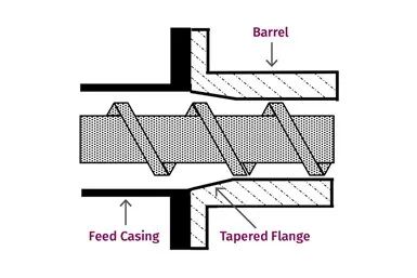
Figure 3 is a schematic diagram of the temporary measures taken to remove the worn cartridge case and the protruding part formed by the new barrel.
Remove the barrel from the extruder and grind the barrel inlet diameter to match the diameter of the feed housing. The barrel has a taper of approximately 0.5 inches, and at this point, the barrel diameter is the original factory diameter. Reinstall the modified barrel onto the extruder and align it with the gearbox. With this configuration, there will be no protrusions that could potentially restrict the flow of pellets.
After restarting the extruder with the improved barrel, the extruder’s performance was restored to its original state, the extrusion rate returned to 100%, and the motor current no longer fluctuated.The improved barrel eliminates the protrusion and restrictions at the connection between the feed sleeve and the barrel, allowing time for the construction of a new feed sleeve.
Due to the different wear rates of the screw, barrel, and feed cylinder, it is important to measure these components regularly. In addition, each time the barrel is replaced, it should be removed to assess the wear condition on the feed cylinder. When installing a new barrel, it should always be aligned with the gearbox; misalignment of the barrel can cause severe wear, thereby shortening the service life of the components.
【Copyright and Disclaimer】The above information is collected and organized by PlastMatch. The copyright belongs to the original author. This article is reprinted for the purpose of providing more information, and it does not imply that PlastMatch endorses the views expressed in the article or guarantees its accuracy. If there are any errors in the source attribution or if your legitimate rights have been infringed, please contact us, and we will promptly correct or remove the content. If other media, websites, or individuals use the aforementioned content, they must clearly indicate the original source and origin of the work and assume legal responsibility on their own.
Most Popular
-

AI Computing Power Demand Ignites Electronic Fabrics! China Jushi Hits Limit Up! Domestic Substitution Welcomes Golden Window
-

Focus on going global! kingfa sci. leads, huitong, preter, and kumho nire follow, china’s modified plastics frenziedly expanding worldwide
-

Back-to-back major joker moves! covestro’s 1.32 million ton mdi dual-line expansion and hdi acquisition reshape global polyurethane landscape
-

Evonik Parts Ways With The Polyester Business! A Strategic Retreat By A Germany Chemical Giant And The Global Industry Shift
-

PA66 Cost and Profit: Broad-Based Weakness in the Feedstock Market Continues to Erode Cost Support for PA66 (202606)