Product Content
Category
Construction Materials-Other Building Materials
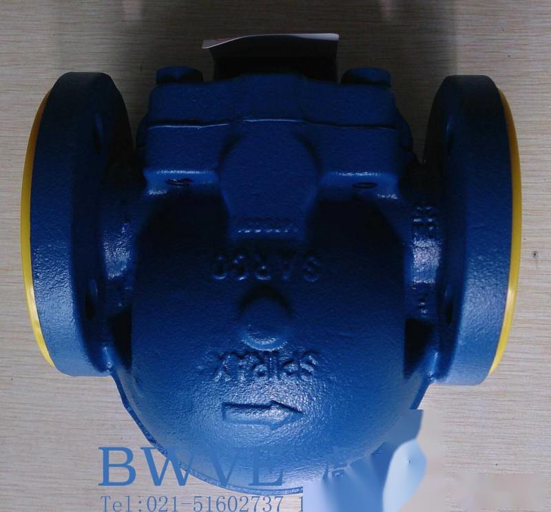
**Spirax Sarco FT14 Steam Trap, Spirax Sarco FT14-10 Steam Trap, Spirax Sarco FT14 Float Operated Steam Trap**.
**1. Spirax Sarco FT14 Steam Trap Overview**: The FT14 is a cast iron-bodied float-operated steam trap with stainless steel internal components. It features a built-in air vent and is available in sizes of 1'' HC (high capacity), 11/9'', 11/z'', and 2''. It is designed for horizontal installation and has threaded connections, with an optional manual adjustment needle valve for use as a blow-off steam lock device, type FT14-C. If needed, holes can be drilled and tapped on the valve cover for 3/a''I3SP or NPT for the installation of a drain valve or balance pipe. Note: For more detailed information, refer to Technical Information Manuals TT-802-27 and TT-802-28.
- **2. Connection Sizes and Pipe Connections**: Available sizes include 1'', 11/9'', 11/z'', and 2'' with threaded connections I38P or NPT.
- **3. Limiting Conditions (ISO 6552)**
- **4. Operating Range**: Note: Carefully read the "Safety Information" in Section 1 before operating the equipment. Refer to the equipment service guide, nameplate, and technical information manual to ensure the product meets the equipment requirements.
2.1 Check the maximum values of material, pressure, and temperature. If the product's operating conditions are below those of the system it is installed in, ensure that the system has adequate overpressure protection.
2.2 Check that the installation position and flow direction are correct.
2.3 Remove protective covers from all connections.
2.4 Install the steam trap in the direction indicated by the arrow on the valve body and maintain the float arm in a horizontal position to ensure its vertical movement. Note: The flow direction for the 1' HC and 11/9'' FT14 is from left to right when viewed from the flange end of the valve body. The flow direction for other sizes is from right to left.
**Spirax Sarco FT14 Steam Trap Note**: For the 1' HC and 11/9'' steam traps, a removal distance of 160mm (6.3'') is required when taking off the valve cover. For the 11/z' and 2' steam traps, a removal distance of 200mm (7.9'') is required. Note: If the steam trap discharges to the atmosphere, ensure it is directed to a safe location, as the temperature of the discharged liquid can reach 100°C (212°F).
**Commissioning**: After installation or maintenance, ensure the system is capable of full operation. Test the operation on alarm or protective devices.
**Operation**: The **Spirax Sarco FT14 Steam Trap** features continuous discharge capability, immediately discharging condensate as it forms. Initially, the thermal static discharge valve eliminates air from the main valve to prevent locking. The hot condensate then seals the discharge valve, and when condensate reaches the steam trap chamber, the float arm mechanism opens the main valve to continuously discharge condensate. When steam arrives, the float lowers, closing the main valve. The float-operated steam trap exhibits features such as high load during startup, good sealing performance, and protection against water hammer and shocks.
**Note**: Please read the "Safety Information" in Section 1 carefully before performing any maintenance operations.
**Warning**: The valve cover gasket contains a thin stainless steel reinforcing ring, which can cause cuts if mishandled.
**3.1 Overview**: Steam trap maintenance can be performed on the pipeline. When reinstalling, ensure all contact surfaces are clean and there are locating pins in the valve cover.
**3.2 Installation of the Main Valve Assembly**:
- For sizes 1’ and 1i/n':
- Remove the valve cover from the valve body.
- Loosen the brackets, pivot brackets (14 and 15), and valve seats (5 and 6).
- Ensure the valve seat/gasket surfaces are clean and dry.
- Install the valve seat into the valve body (5 and 6 with gasket adhesive).
- Use the installation bolts to secure the brackets and pivot brackets into the valve body, but do not tighten yet.
- Align the valve body and small holes, securing them with locating pins, and install the float arm on the pivot bracket.
- Tighten the installation bolts (7) to the recommended torque (see Table 1).
- Re-tighten the valve cover bolts/nuts (2) to the recommended torque (see Table 1).
- For sizes 1 1/2' and 2':
- Loosen the 4 installation bolts or nuts (7).
- Remove the valve assembly (5, 6, and 7) and install the new one.
- Tighten the installation bolts or nuts (7) diagonally to the recommended torque (see Table 1).
- Install the valve cover and gasket ensuring the locating pin position is correct.
- Re-tighten the valve cover bolts/nuts (2) to the required torque (see Table 1).
**3.3 Installation of the Discharge Valve Assembly**:
- Remove the spring, sealing diaphragm, and spacer.
- Remove the valve seat.
- Install the new valve seat and bracket and tighten to the recommended torque (see Table m).
- Install the spacer, sealing diaphragm, and spring.
**Available Spare Parts**:
Main valve assembly with float (1'', 1 1/4'') 5, 6, 7, 8, 14, 15, 17
Valve assembly with anti-cavitation baffle (11/2'', 2'') 5, 6, 7, 18
Float (11/2'')
Discharge valve assembly 9, 10
Blow-off steam lock and discharge valve assembly 9, 10, 11, 12
Gasket set (3 pieces) 3, 6, 7, 10, 12
**Note**: Anti-cavitation baffles for sizes 1'' and 11/4'' are embedded in the valve body during manufacturing and are no longer provided as separate parts.
**Ordering Spare Parts**: Order spare parts according to the "Available Spare Parts" list and specify the steam trap's nominal diameter and type. Example: Discharge valve assembly for Spirax Sarco 2'' PT14 steam trap.
The above content is provided by Bilvie Company (www.bilvie.com). Please indicate the source when reproducing the article.
The company also supplies similar products: **Spirax Sarco Steam Traps, Spirax Sarco Float Operated Steam Traps, Spirax Sarco FT14 Steam Traps**.


 Whats App
 Plastmatch App
Scan the QR code
Plastmatch App
Scan the QR code