


In-Depth Analysis of Conveying Efficiency and Wear in Large Twin-Screw Extruders Based on Discrete Element Method (DEM)
Large co-rotating twin-screw extruders play an important role in the field of polyolefin compounding and are widely used in the plastics, food, and chemical industries. Due to their excellent mixing, conveying, shearing, and dispersing capabilities, as well as good self-cleaning properties, they have irreplaceable advantages, especially in the processing and compounding of polyolefin materials.
The solid conveying characteristics of large twin-screw extruders are significantly affected by factors such as screw speed and material properties, which can lead to decreased stability in the conveying process.
The article adoptsDiscrete Element Method(DEM) correctSystematic study on the pellet conveying performance and screw wear patterns in the solid conveying section of large co-rotating twin-screw extrudersUsing EDEM simulation software to analyze the effect of different material fill rates on particles in the conveying section.Distribution, transmission rate, velocity distribution, and force characteristics.The impact, revealingParticle motion patterns and screw wear characteristics.
Mathematical Model
The discrete element method obtains the overall motion behavior of particles by establishing a particle contact force model and solving their equations of motion.
The particles in the material undergo both translational and rotational motion, both of which are governed by Newton's second law. The corresponding mathematical expressions are:
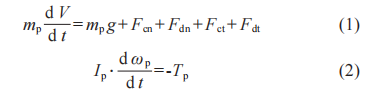
In equations (1) to (2): mp is the mass of the particle, kg; V is the velocity of the particle, m/s; g is the gravitational acceleration, m/s²; F is the force on the particle, N; Fcn is the elastic restoring force in the normal direction of the contact surface, N; Fdn is the viscous damping force in the normal direction of the contact surface, N; Fct is the elastic restoring force in the tangential direction of the contact surface, N; Fdt is the viscous damping force in the tangential direction of the contact surface, N; Ip is the inertia tensor of the particle, kg·m²; ωp is the angular velocity of the particle, rad/s; Tp is the torque of the particle, N·m. The definition of Tp is:
In equation (3): R is the position vector of the particle, in meters (m).
In the process of solid conveying with twin screws, there exist complex interactions such as elastic deformation, viscous damping, and friction between particles as well as between particles and the wall. The Hertz-Mindlin contact model can incorporate these interactions to accurately describe the normal and tangential contact behaviors between particles, thereby more precisely reflecting the characteristics of particles in the screw meshing zone and the free conveying zone.
The Hertz-Mindlin contact model is used to calculate the contact force between particles or between particles and the wall. The definition of the normal direction elastic restitution force Fcn in this model is:
In equation (4): E* is the average elastic modulus of the contacting particles, in GPa; R* is the average particle radius, in meters; δn is the normal overlap, in meters. The definition of the normal viscous damping force Fdn is:
In equation (5): mp is the particle mass, kg; Vn is the relative velocity in the normal direction, m/s; the viscous damping coefficient β and the damping coefficient in the normal direction Sn are given by equations (6) and (7), respectively; e is the coefficient of restitution.
The definition formula of the elastic restoring force Fct in the tangential direction of the contact surface is:
In Equation (8): δt is the overlap in the tangential direction, in meters (m). The tangential viscous damping coefficient (St) is given by Equation (9):
In Equation (9): G* is the average shear modulus, in GPa. In addition, the relationship between the shear modulus (transverse elastic coefficient) G, the elastic modulus (longitudinal elastic coefficient) E, and Poisson's ratio ν is as follows:
The calculation formula for the tangential viscous damping force Fdt is as follows:
In equation (11): Vt is the relative velocity of the particle in the tangential direction, in m/s. The tangential force is limited by Coulomb friction, and slip can be considered to occur when the following condition is satisfied:
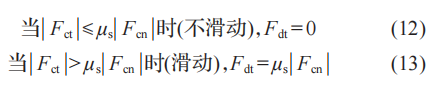
In Equations (12) to (13): μs is the coefficient of static friction.
Simulation Model and Parameter Settings
1
Simulation Model Establishment
This paper mainly studies the solid conveying section of the twin screw. To be consistent with the actual situation, the opening at the end of the geometric model is the same as the barrel diameter. To reduce the influence of the feeding position and speed on the conveying characteristics, the feeding port is set directly above the screw, with a width matching that of the barrel to ensure uniform distribution of the material, thereby studying the conveying function of the screw.
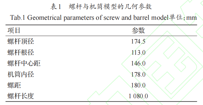
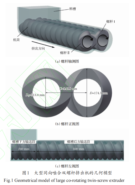
Use SolidWorks to create a twin-screw model, with the barrel modeled as a whole, and the threaded elements assembled onto the mandrel in a modular way to form a complete structure with the barrel. The screw engagement is placed inside the barrel, ensuring synchronous rotation without friction or collision. Table 1 shows the geometric parameters of the screw and barrel model, and Figure 1 shows the geometric model of the large co-rotating twin-screw extruder.
2
Simulation parameter settings
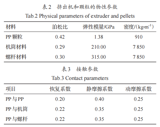
This study uses spherical polypropylene (PP) particles with a diameter of 4 mm as the conveying material. The screw material is selected as 34CrAlNi7-10 alloy steel, which is wear-resistant, corrosion-resistant, and has high toughness. The barrel adopts an integral structure of 31CrMoV9 alloy steel. The contact model between the particles, the extruder, and among the particles is based on the Hertz-Mindlin model.
To rapidly fill the hopper and ensure a stable conveying process, particles are given an initial velocity of 0.1 m/s along the y-axis when generated on the hopper surface. Table 2 lists the physical properties of the extruder and particles, while Table 3 provides the contact parameters. In the simulation setup, the Rayleigh time step is set to 20%, the contact search range is three times the particle diameter, and the total simulation time is 15 seconds.
3
Basic Assumptions
Due to friction and shear forces, heat is generated during the conveying process of particles, which in turn affects the physical and chemical properties of the material.
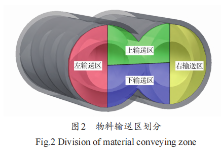
Therefore, the following assumptions are made in the simulation: the particles are rigid bodies, remain spherical, and are not subject to adhesion or liquid bridge forces due to heat, with a constant coefficient of friction. Based on the distribution of materials in the barrel, the twin-screw conveying area is divided into four sections, and the conveying capacity of each section is calculated to obtain the total conveying capacity. Figure 2 shows the division of the material conveying area.
Simulation Results Analysis
To study the effect of material fill rate on the particle conveying characteristics and screw wear in the solid conveying section of a large co-rotating twin-screw extruder, a spherical particle model was established using EDEM simulation software. At a screw speed of 150 r/min, four sets of simulation experiments with different fill rates were conducted while keeping parameters such as material density, restitution coefficient, and dynamic friction coefficient constant. Through EDEM post-processing, sections perpendicular to the barrel at three screw pitches (540 mm) were selected for analysis.
1
Analysis of Solid Conveying Characteristics under Different Fill Rates
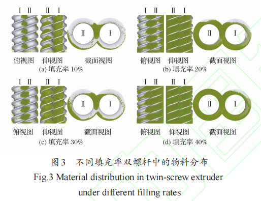
Figure 3 shows the material distribution in the twin-screw extruder at different filling ratios. It can be seen from Figure 3 that the material distribution in the twin-screw extruder varies significantly under different filling ratios.
From Figures 3a and 3b, it can be seen that when the material filling rate is low, most of the material accumulates below Screw I and Screw II, namely in the lower conveying area, and some material also accumulates in the upper half of the meshing area. After the material enters the feed hopper, it is concentrated in the area below the screw due to the rotational motion of the screw and gravity, while some accumulates in the upper half of the meshing area under the influence of gravity. The material in the meshing area is pushed by the screw threads and is conveyed in a positive displacement manner along the axis of the screw.
From Figures 3c and 3d, it can be observed that with the increase in material filling rate, the left conveying area is filled first. When the filling rate reaches 30%, the material exhibits more "∞"-shaped movement in the screw. Therefore, it can be predicted that with the further increase in the filling rate, the right conveying area will be the last to be filled.
2
The Influence of Different Filling Rates on Conveying Speed and the Conveyed Volume in Each Subregion
Figure 4 shows the conveying rate at different fill rates.
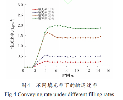
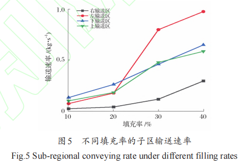
As shown in Figure 4, in twin-screw solid conveying, different filling rates have a significant impact on the conveying rate. Under the same conditions, the higher the material filling rate, the greater the conveying capacity. Especially when the filling rate increases from 20% to 30%, the conveying rate shows a significant improvement. With the increase of simulation time, the conveying rate exhibits a trend of first increasing and then slightly decreasing. Overall, the material filling rate significantly affects the conveying rate of the twin screws. As the filling rate increases, particularly in the range of 20% to 30%, the improvement in conveying rate is most pronounced. Additionally, at the initial stage of the simulation, due to the pre-feeding effect, the conveying rate shows a phased peak. Figure 5 shows the conveying rates in subzones under different filling rates.
As shown in Figure 5, with the increase of material filling rate, the region with the highest material conveying capacity shifts gradually from the lower conveying zone to the left conveying zone. This is because, under low filling rate conditions, the vertically fed material particles fall into the intermeshing region of the screw due to gravity. Since the gap in the upper intermeshing region of the screw is relatively small, material accumulates in the upper intermeshing region. Once this area is filled, subsequent material is carried into the lower conveying zone by the combined effects of screw rotation and gravity. Therefore, at low filling rates, the lower conveying zone has the highest conveying capacity. As the filling rate increases, the left conveying zone gradually becomes the region with the largest material conveying capacity. When the material filling rate increases from 20% to 30%, the filling rate in the left conveying zone increases significantly. This is because the geometric volume of the screw groove in the left conveying zone is larger than that in the upper and lower conveying zones, resulting in the conveying capacity of the left conveying zone generally being higher than that of the upper and lower conveying zones under the same material filling rate.
3
The impact of different filling rates on the speed and force of the material
Figure 6 shows the velocity and velocity vectors of particles in a screw under different fill rates.
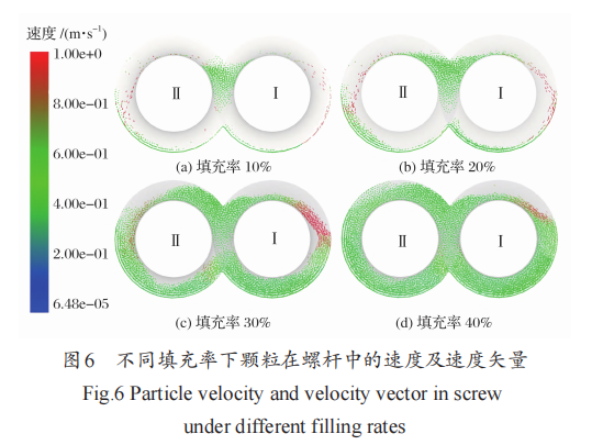
As shown in Figure 6, with the increase of material filling rate, the particle velocity distribution gradually becomes more uniform, with the highest particle velocity observed in the right conveying zone. This is the result of the combined effects of the screw geometry and gravity. When the material accumulation height in the meshing zone reaches the root diameter of the screw, Screw I carries the material out of the meshing zone and throws it onto the inner wall of the non-meshing zone, thereby increasing the velocity in the right conveying zone. In addition, after the filling rate increases, the material velocity in the meshing zone significantly rises, mainly due to the enhanced shear and extrusion forces of the screw, which intensify the material movement in this area. Therefore, under high filling rate conditions, the right conveying zone and the meshing zone become the key areas for material transport.
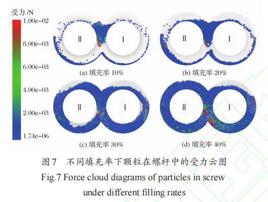
Figure 7 shows the stress distribution cloud maps of particles in the screw under different filling rates. As can be seen from Figures 7a and 7b, at low filling rates, the boundaries of each sub-conveying zone are clear, the particles in the meshing zone experience the strongest forces, and the material in the upper meshing zone is subjected to intense shear and extrusion. From Figures 7c and 7d, it can be observed that with the increase of filling rate, the materials in the upper and lower conveying zones jointly participate in the meshing process, and the particles just entering the meshing zone reach peak stress. Despite the increase in filling rate, gravity still affects particle movement, the boundaries of each zone remain, and the meshing zone consistently bears the highest concentration of stress. Therefore, the variation in filling rate significantly influences the stress distribution of particles, and the meshing zone plays an important role in the material conveying process.
4
The impact of different fill rates on screw wear
Figure 8 shows the distribution cloud map of screw wear amount corresponding to different fill rates.
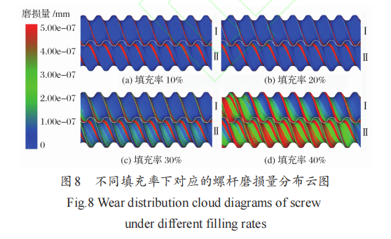
From Figure 8, it can be seen that with the increase of the filling rate, screw wear intensifies, concentrating on the top of the screw flight, while the wear area on the thrust surface gradually expands and extends to the back of the screw flight and the root of the screw. In comparison, the wear increase of Screw I is less than that of Screw II. This is because during particle conveying, impact and friction are the main causes of wear, and the top of the screw flight experiences the most obvious wear due to frequent contact and greater force. The increase in filling rate enlarges the particle contact area, resulting in an increase in both the amount and range of wear. However, the filling degree in the right conveying zone is relatively low, and the contact area is small; its wear is mainly caused by particles accumulated in the meshing area, with a smaller increase.
Figure 9 shows the variation of screw wear depth under different filling rates. As can be seen from Figure 9, both the average wear depth and the maximum wear depth of the screw per unit time increase with the rise of material filling rate, and the higher the filling rate, the greater the wear rate. When the filling rate increases from 10% to 40%, the average wear depth increases by about 77.9%, and the maximum wear depth increases by 36.4%. This is because the increase in filling rate expands the contact area between the particles and the screw, thereby intensifying overall wear. However, under low filling rates, the force distribution of the material in the screw is relatively uniform, resulting in a relatively small increase in maximum wear depth.
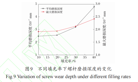
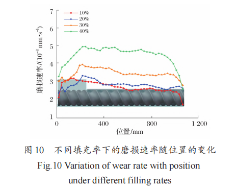
Figure 10 shows the variation of wear rate with position under different fill rates. As can be seen from Figure 10, the wear depth along the axial position exhibits significant changes under different fill rates. The screw beneath the trough in the conveying section experiences significantly more wear than the rear section, with the wear rate reaching its maximum at the inlet and gradually decreasing with increasing axial distance. The decrease is particularly pronounced near the outlet. Although similar trends are observed under different fill rates, near the outlet (around 900 mm), the wear rate drops sharply at fill rates of 30% and 40%, while the decrease is more gradual at fill rates of 10% and 20%.
Under different fill rate conditions, the distribution patterns of the material inside the twin screw differ significantly. As the fill rate increases, the fill degree in the conveying section increases; the left conveying zone typically fills up earlier, while the right conveying zone fills more slowly. At high fill rates, the material movement exhibits an "∞"-shaped conveying pattern.
Simulation results indicate that a higher material filling rate enhances the conveying rate, with this increase being particularly significant when the filling rate rises from 20% to 30%. The increase in filling rate gradually makes the particle velocity distribution more uniform, with particle velocity reaching its maximum in the right conveying zone.
Under high filling ratios, the particles in the meshing zone experience greater forces, exhibiting more intense motion characteristics. This area remains the focal point of particle force concentration under different filling ratios.
With the increase of the fill rate, the wear of the screw intensifies, mainly concentrated on the top of the screw flights. Both the average and maximum wear depths per unit time significantly increase with the fill rate, with the wear amount at 40% fill rate being much greater than that at 10% fill rate. Axial observation shows that the wear rate is highest in the inlet section and gradually decreases near the outlet, which is consistent under different fill rate conditions.
In summary, the material fill rate is an important variable affecting the solid conveying performance and screw wear of twin-screw extruders. Appropriately increasing the fill rate can help improve the conveying rate, but it will also exacerbate wear on key parts. Therefore, optimizing the fill rate and screw design can achieve a balance between improving conveying efficiency and equipment durability, thereby enhancing industrial production efficiency and equipment lifespan.
【Copyright and Disclaimer】The above information is collected and organized by PlastMatch. The copyright belongs to the original author. This article is reprinted for the purpose of providing more information, and it does not imply that PlastMatch endorses the views expressed in the article or guarantees its accuracy. If there are any errors in the source attribution or if your legitimate rights have been infringed, please contact us, and we will promptly correct or remove the content. If other media, websites, or individuals use the aforementioned content, they must clearly indicate the original source and origin of the work and assume legal responsibility on their own.
Most Popular
-

AI Computing Power Demand Ignites Electronic Fabrics! China Jushi Hits Limit Up! Domestic Substitution Welcomes Golden Window
-

Focus on going global! kingfa sci. leads, huitong, preter, and kumho nire follow, china’s modified plastics frenziedly expanding worldwide
-

Back-to-back major joker moves! covestro’s 1.32 million ton mdi dual-line expansion and hdi acquisition reshape global polyurethane landscape
-

Evonik Parts Ways With The Polyester Business! A Strategic Retreat By A Germany Chemical Giant And The Global Industry Shift
-

PA66 Cost and Profit: Broad-Based Weakness in the Feedstock Market Continues to Erode Cost Support for PA66 (202606)