


Guizhou Provincial People's Hospital: Selective Distribution of In Situ Microfiber-Constructed β-Nucleating Agents and Their Effects on the Structure and Properties of Polypropylene (PP)
Abstract: β-EVOH was prepared by melt blending β-nucleating agent (TMB-5) and ethylene-vinyl alcohol copolymer (EVOH) through a twin-screw extruder. Using a micro-nano layered co-extrusion device, the β-EVOH phase was in-situ micro-fibrillated within the isotactic polypropylene (iPP) phase, constructing selective distribution of the β-nucleating agent, resulting in β-EVOH/iPP in-situ micro-fibril composites. Under the combined effects of the flow field, micro-fibril phase, and selective distribution of the β-nucleating agent, the influence of β-EVOH content on the multiscale microstructure, crystallization performance, mechanical properties, and barrier properties of the composites was investigated. The results show that under the intense shear-stretch flow field of the micro-nano layered co-extrusion device, β-EVOH within the selected content range (mass fraction 5%~50%) can form micro-fibrils in iPP, resulting in a phase morphology structure where lamellar micro-fibrils coexist with cylindrical micro-fibrils. In the original extruded samples of β-EVOH/iPP in-situ micro-fibril composites, only α-crystals formed. β-crystals could only form during the recrystallization of iPP when samples were melted at high temperatures, eliminating the flow field's influence and providing the driving force for the β-nucleating agent to migrate from the fibrous phase to the interface. With increasing β-EVOH phase content, the tensile strength of β-EVOH/iPP in-situ micro-fibril composites first increases and then remains relatively unchanged, the nominal strain at break first increases and then decreases, and the water vapor transmission rate gradually decreases, primarily due to differences in phase morphology structure.
Keywords: polypropylene; in-situ microfibrils; selective distribution of nucleating agents; crystallization properties; mechanical properties; barrier properties
Isotactic polypropylene (iPP) has the advantages of low density, good mechanical properties, resistance to chemical reagents, and ease of processing and molding. It is widely used in fields such as automobiles, packaging, and household appliances. As a semi-crystalline polymer, the macroscopic properties of iPP largely depend on its crystallization behavior, such as crystal form.[1-2]Crystal content[3-4] Crystal size[5-6]And crystal morphology[7-8]Therefore, achieving high performance of iPP through crystallization control has always been a hot research topic. Common crystallization control methods include the addition of nucleating agents.[9-10]Control external crystallization conditions[11]Flow field crystallization[12-14]Constrained crystallization[15-17]With the development of polymer processing technology, a variety of regulation methods are currently often combined to control the crystallization of iPP, thereby optimizing its properties. For example, Bai et al.[18]and Zhou et al.[19]In the processing process, a strong flow field is applied to the melt, combined with a nucleating agent, to impart the product with a large number of oriented, distributed, interlocking shish-kebab structures with adjacent lamellae interpenetrating each other. This "interlocking" shish-kebab structure has unique advantages in simultaneously enhancing the barrier properties and mechanical properties of the material. Luo et al.[7]By regulating the crystallization of iPP through nucleating agents and external processing conditions, it was found that the melt processing temperature significantly influences the morphology formed by the self-assembly of nucleating agents, thereby inducing the formation of different crystal morphologies and resulting in differentiated iPP composites.
1 Experimental Section
1.1 Main Raw Materials
iPP: F401, Melt Flow Rate (MFR) of 3.0 g/10 min (230 ℃, 2.16 kg), density of 0.9 g/cm³3China Petroleum & Chemical Corporation Yangzi Petrochemical Co., Ltd.
EVOH: EV3201F, containing 32% by mass of ethylene, MFR of 1.6 g/10 min (190 ℃, 2.16 kg), Suzhou Dije Plastic Chemical Co., Ltd.;
Replacement of arylacetamide β-nucleating agents: TMB-5, Shanxi Chemical Research Institute.
1.2 Major Instruments and Equipment
Co-rotating twin-screw extruder: CTE20, Coperion Keya (Nanjing) Machinery Co., Ltd.
Differential Scanning Calorimeter (DSC): Q10, Waters Corporation, USA.
Scanning Electron Microscope (SEM): Quanta 250 FEG SEM, FEI Company, USA.
Microcomputer-controlled electronic universal testing machine: CMT6104, Meters Industrial Systems (China) Co., Ltd.;
Water Vapor Transmission Rate Tester: MOCON 3/33 MA, MOCON Company, USA;
Micro-nano multilayer co-extrusion device: self-made.
1.3 Sample Preparation
(1) Preparation of β-EVOH dispersion phase: The β nucleating agent and EVOH were dried in an oven at 70 °C for 12 hours. Then, 2 wt% of the β nucleating agent was evenly mixed with EVOH and extruded using a co-rotating twin-screw extruder to obtain the β-EVOH dispersion phase. The screw speed of the extruder was 150 r/min, and the temperatures of the zones were set at 100, 180, 200, 200, and 200 °C, respectively.
(2) Preparation of β-EVOH/iPP in-situ microfibrillar composites: After drying the β-EVOH dispersed phase and iPP in an oven at 70 °C for 12 hours, β-EVOH and pure iPP were uniformly mixed at mass fractions of 5%, 10%, 20%, 30%, 40%, and 50%. The β-EVOH/iPP in-situ microfibrillar composites were prepared using a micro/nanolayer co-extrusion device. The samples were respectively labeled as 5%-EVOH/iPP, 10%-EVOH/iPP, 20%-EVOH/iPP, 30%-EVOH/iPP, 40%-EVOH/iPP, and 50%-EVOH/iPP. The temperatures of the extruder zones of the micro/nanolayer co-extrusion device were set at 100, 180, 200, 200, and 200 °C, respectively, while the layer multiplier and die temperatures were both set at 200 °C. The screw speed of the extruder was 200 r/min, and the three-roll traction speeds from top to bottom were 80, 70, and 60 r/min, respectively.
1.4 Testing and Characterization
1.4.1 SEM Testing
Cut the prepared β-EVOH/iPP in-situ microfibrillar composite sheets into strips measuring 1.5 cm × 1 cm perpendicular to the extrusion direction. After quenching in liquid nitrogen for 2 hours, fracture the samples. The fracture surfaces were gold-sputtered and observed by SEM to examine the microstructure. To further observe the morphology of the β-EVOH dispersed phase, cut β-EVOH/iPP in-situ microfibrillar composite sheet samples into 2 cm × 2 cm pieces for etching. The sheets were placed in boiling xylene for 2 hours to dissolve and remove the iPP matrix phase, obtaining etched samples. After drying, the etched samples were gold-sputtered and the morphology of the β-EVOH dispersed phase was observed.
1.4.2 DSC Test
2In the atmosphere of (N2At a rate of 50 mL/min, the sample was heated to 200 °C at a rate of 10 °C/min and held at this temperature for 5 minutes to obtain the first melting curve. Subsequently, the sample was cooled to room temperature at 10 °C/min to obtain the crystallization curve, and then reheated to 200 °C at 10 °C/min to obtain the second melting curve. The sample mass was 6–8 mg.
1.4.3 Tensile Performance Test
Cut the β-EVOH/iPP in-situ microfibrillar composite sheet into dumbbell-shaped standard specimens with a length of 75 mm and a width of 10 mm along the extrusion direction. Before testing, all specimens were placed at room temperature for 24 hours. Tensile performance tests were conducted at room temperature using a universal testing machine with a tensile rate of 100 mm/min. The average value of 5 specimens was taken as the test result.
1.4.4 Water Vapor Transmission Rate Test
The water vapor transmission rate was tested according to GB/T 1037-1988. Test specimens were selected to be free of damage and creases, with uniform thickness, and were cut into fixed sizes using a mold. The water vapor transmission rate of the β-EVOH/iPP in-situ microfibrillar composite sheets was measured using a water vapor transmission tester. Three parallel samples were tested for each group, and the average value was calculated.
2 Results and Discussion
2.1 Morphological Analysis of β-EVOH/iPP In Situ Microfibrillar Composites
Figure 1 shows the SEM images of β-EVOH/iPP in-situ microfibrillar composites with β-EVOH mass fractions of 5%, 10%, 20%, 30%, 40%, and 50%. From Figure 1, it can be observed that as the β-EVOH mass fraction varies from 5% to 50%, β-EVOH can form microfibers in situ within the iPP. Meanwhile, most β-EVOH microfibers are aligned along the horizontal extrusion direction, with only a few β-EVOH microfibers being pulled out from the iPP matrix during the brittle fracture process in liquid nitrogen, resulting in a random arrangement. From the morphology of the pulled-out β-EVOH microfibers, it can be seen that some β-EVOH dispersed phases evolve into a lamellar structure. As the β-EVOH content increases, the number of formed microfibers gradually increases, but it is difficult to clearly distinguish the morphological differences of the microfibers with different β-EVOH contents.
To further observe the morphology of β-EVOH microfibers, the matrix phase iPP was etched using boiling xylene, leaving only the undissolved β-EVOH microfibers, as shown in Figure 2. As seen in Figure 2a, when the mass fraction of β-EVOH is 5%, the β-EVOH phase mainly exists as cylindrical microfibers, accompanied by some undeformed β-EVOH spheres. When the mass fraction of β-EVOH is 10% and 20%, the β-EVOH phase is mainly composed of flaky microfibers, along with cylindrical microfibers. When the mass fraction of β-EVOH increases to 30% or above, the β-EVOH phase primarily consists of cylindrical microfibers with smaller diameters, accompanied by a few flaky microfibers. The in-situ microfibrillation process involves deformation, collision, fusion, and deformation of the polymer dispersed phase under the action of a force field. The component ratio is a key factor affecting this process and the final properties of the material.[26]As the dispersed phase content increases, the number of dispersed phase particles increases, enhancing the aggregation between particles and increasing the probability of collision, which easily leads to the formation of fibers with larger aspect ratios and volumes. If the dispersed phase content is too low, the dispersed phase melt particles find it difficult to undergo significant deformation, making it hard to form microfibers. If the dispersed phase content is too high, it may lead to the formation of large ellipsoidal particles or even a co-continuous structure.
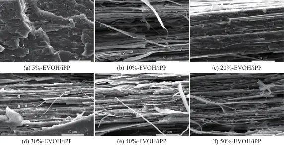
Fig. 1 SEM images of β-EVOH/iPP in-situ microfibrillar composites with different β-EVOH mass fractions
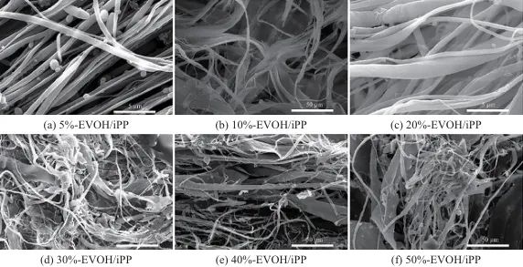
Fig. 2 SEM photos of β-EVOH micro-fiber of β-EVOH/iPP in-situ micro-fiber composites with different β-EVOH mass fractions after etching iPP
2.2 Crystallization Performance Analysis of β-EVOH/iPP In-situ Microfiber Composites
The β nucleating agent is dispersed in the EVOH phase and gradually changes its distribution position in the iPP composite material along with the in-situ microfibrillation process of the EVOH phase. Ultimately, due to the formation of EVOH microfibers, an oriented fibrous distribution is formed in the iPP. The influence of the flow field, microfiber phase, and selective distribution of the β nucleating agent on the crystallization and melting behavior of iPP was investigated using a DSC instrument. Figure 3 shows the effect of the change in β-EVOH content on the crystallization behavior of β-EVOH/iPP in-situ microfiber composites, with specific crystallization and melting parameters listed in Table 1. As seen in Figure 3, the β-EVOH/iPP in-situ microfiber composites exhibit two crystallization peaks, corresponding to the EVOH crystallization peak and the iPP crystallization peak, respectively.
With the increase of β-EVOH content, the crystallization peak position of EVOH does not show significant changes, while the peak area gradually increases. This indicates that the β-nucleating agent in EVOH does not affect the crystallization of EVOH. Unlike EVOH, with the introduction and variation of β-EVOH content, the crystallization peak position of iPP changes significantly. When the mass fraction of β-EVOH is 5%, the crystallization peak of iPP shifts from 115 ℃ to 128 ℃, and the crystallization ability is significantly enhanced, indicating that β-EVOH has a heterogeneous nucleation effect on iPP. As the β-EVOH content further increases, the crystallization temperature of iPP first decreases, dropping to 125 ℃ at a β-EVOH mass fraction of 20%, and then rises again to 127 ℃ (as shown in Table 1). In previous studies, pure EVOH microfibers could only raise the crystallization temperature of iPP to 124 ℃, whereas the crystallization temperatures of β-EVOH/iPP in-situ microfiber composites are all at or above 125 ℃, indicating that the β-nucleating agent in the EVOH phase migrates to the iPP phase and induces iPP crystallization, demonstrating a synergistic promotion effect on iPP crystallization compared with EVOH microfibers. The differences in crystallization temperature among various β-EVOH contents are mainly attributed to microfiber morphology (as shown in Figure 2), where different microfiber morphologies have different specific surface areas and thus exhibit varying numbers of nucleation sites.
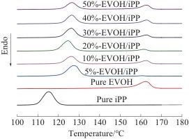
Fig. 3 DSC crystallization curves of β-EVOH/iPP in-situ microfibrillar composites with different β-EVOH mass fractions
Table 1 Crystallization and melting characteristic temperatures of β-EVOH/iPP in-situ micro-fiber composites
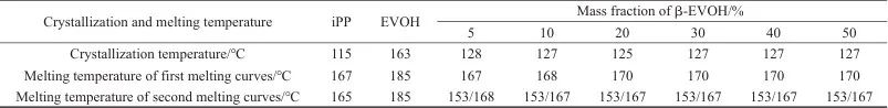
The changes in the crystal form of iPP under the combined effects of the flow field, microfibrillar phase, and selective distribution of β-nucleating agents were further investigated through DSC melting curves and XRD. Figure 4 shows the DSC melting curves of β-EVOH/iPP in situ microfibrillar composites. From Figure 4, it can be seen that there is a significant difference between the first and second melting curves of the β-EVOH/iPP in situ microfibrillar composites. From the first heating curve of the DSC in Figure 4a and the data in Table 1, it is known that the β-EVOH/iPP in situ microfibrillar composite has two melting peaks, corresponding to the melting peak of the EVOH phase and the iPP phase, respectively. As the β-EVOH content increases, there is no significant change in the position of the EVOH phase melting peak, while the melting peak of the iPP phase shifts 1–3 ℃ higher than that of pure iPP, reaching up to 170 ℃, which is typical of the polypropylene α-crystal form. This indicates that the effect of β-EVOH content is merely to shift the peak position toward higher temperatures, meaning that the higher the β-EVOH content in the sample, the more perfect the iPP crystallization, resulting in thicker lamellae and a higher melting point. No β-crystals were found besides the α-crystal form. Unlike the first melting curve, the second melting curve of the β-EVOH/iPP in situ microfibrillar composites has three melting peaks, with an additional melting peak at 153 ℃, which is the β-crystal melting peak. This means that β-crystals were not formed in the extruded original sheets, but when the sheets were melted at high temperatures and then recrystallized upon cooling, β-crystals were formed. To verify this phenomenon, the extruded sheets were fixed in a mold, melted, and recrystallized, and the crystal form changes were examined using XRD.
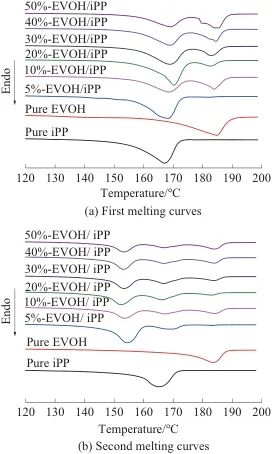
Fig. 4 DSC melting curves of β-EVOH/iPP in-situ micro-fiber composites with different β-EVOH mass fractions
Figure 5 shows the XRD patterns of β-EVOH/iPP in situ microfibrillar composites. From the XRD curves, it can be seen that only the α-form (110), (040), and (130) crystal planes are present in the β-EVOH/iPP in situ microfibrillar composite extruded sheets (as shown in Figure 5a), while the melt-recrystallized samples exhibit not only the α-form but also the β-form (300) crystal plane (as shown in Figure 5b). Consistent with the results obtained from the DSC melting curves, this further confirms that there is no β-crystal in the original β-EVOH/iPP in situ microfibrillar composite samples, and the β-crystal can only form after the samples undergo melt recrystallization.
The main reason for this phenomenon is that during the micro-nano layer co-extrusion process, the intense shear-stretching flow field not only evolves EVOH into microfibers with a high aspect ratio but also induces iPP molecular chains to orient on the surface of EVOH microfibers, using them as templates. These oriented molecular chains induce the formation of the α-crystal form in iPP and simultaneously hinder the effect of β nucleating agents in the EVOH phase. During the high-temperature melting process, the oriented molecular chains on the surface of these microfibers lose their orientation, while the high temperature provides the driving force for the β nucleating agents to migrate to the surface, promoting the migration of more β nucleating agents. The migrated β nucleating agents not only synergistically promote the crystallization of iPP with EVOH microfibers (as shown in Figure 3) but also induce the formation of the β-crystal form in iPP.
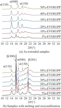
Fig. 5 XRD curves of β-EVOH/iPP in-situ micro-fiber composites with different β-EVOH mass fractions
2.3 Mechanical and Barrier Properties Analysis of β-EVOH/iPP In Situ Microfibrillar Composites
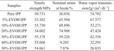
As is well known, the in-situ formation of oriented microfibers in the matrix material is beneficial for improving the mechanical and barrier properties of the matrix material. In this study, the strong shear-stretching complex flow field in the micro-nano layer co-extrusion technology is utilized to in-situ form β-EVOH dispersed phase into microfibers with a high aspect ratio in the iPP matrix, which are oriented along the flow direction. Therefore, it can be expected that the mechanical and barrier properties of iPP will be improved due to the presence of β-EVOH microfibers. Table 2 shows the effects of different β-EVOH contents on the mechanical and barrier properties of β-EVOH/iPP in-situ microfiber composites. As seen from Table 2, the tensile strength and nominal strain at break of pure iPP are 50.731 MPa and 36.036%, respectively. For the sample containing 5% by mass of β-EVOH microfibers (5%-EVOH/iPP), the tensile strength and nominal strain at break increase to 53.202 MPa and 65.594%, respectively. When the content of β-EVOH microfibers is further increased, the tensile strength of the β-EVOH/iPP in-situ microfiber composites increases slightly, while the nominal strain at break first increases and then decreases. This is mainly because of the poor interfacial compatibility between the β-EVOH microfibers and the iPP matrix. When a large amount of β-EVOH is added, there are many weak interfaces between the β-EVOH microfibers and the iPP matrix, which quickly lead to failure during the tensile process, causing the material to break rapidly. Therefore, when the β-EVOH content is too high, the nominal strain at break decreases significantly. Table 2 also lists the water vapor transmission rates of the β-EVOH/iPP in-situ microfiber composites.
It can be seen that compared with pure iPP, the water vapor transmission rate of the sample containing 5 wt% β-EVOH microfibers (5%-EVOH/iPP) decreased from 74.782 g/(m2·d) decreased to 67.377 g/(m2With the increase of β-EVOH content, the water vapor transmission rate of β-EVOH/iPP in situ microfibrillar composites gradually decreases, reaching as low as 26.835 g/(m.2Compared to pure iPP, it decreased by 64.1%. The main reason is that pure EVOH has better barrier properties than iPP. The composite of the two is beneficial to the improvement of the barrier performance of iPP. Meanwhile, under the stretching-shear flow field of micro-nano layer coextrusion, the β-EVOH phase forms oriented microfibers in situ within the iPP, even evolving into lamellar microfibers. This microfiber morphology is similar to a "brick wall" structure. When gas passes through iPP, encountering the β-EVOH barrier phase changes the pathway, thereby significantly extending the gas permeation path and markedly improving the barrier performance of iPP.
Tab. 2 Mechanical and barrier properties of β-EVOH/iPP in-situ micro-fiber composites with different β-EVOH mass fractions
Conclusion
Under the intense shear-stretching composite flow field of micro/nano multilayer co-extrusion, β-EVOH within the selected content range (mass fraction 5%~50%) can in situ form microfibers in iPP. These microfibers are oriented along the horizontal extrusion direction, resulting in a phase morphology where cylindrical and lamellar microfibers coexist.
(2) β-EVOH/iPP in-situ microfibrillar composite extruded raw sheets do not form β-crystals. After the high-temperature melting eliminates the flow field effect and provides mobility for the β-nucleating agent, β-crystals are formed upon recrystallization.
When the mass fraction of (3)β-EVOH microfibers is 20% or below, it has a reinforcing and toughening effect on iPP. With a further increase in the β-EVOH microfiber content, the tensile strength changes little, while the nominal fracture strain decreases to a minimum of 7.876%.
(4) β-EVOH microfibers are oriented in iPP, forming a brick-wall-like phase morphology structure. When gas permeates through iPP, it encounters the β-EVOH barrier phase, which alters the pathway and significantly extends the gas permeation path. The water vapor transmission rate of iPP is reduced to a minimum of 26.835 g/(m²·d).2·d)。
【Copyright and Disclaimer】The above information is collected and organized by PlastMatch. The copyright belongs to the original author. This article is reprinted for the purpose of providing more information, and it does not imply that PlastMatch endorses the views expressed in the article or guarantees its accuracy. If there are any errors in the source attribution or if your legitimate rights have been infringed, please contact us, and we will promptly correct or remove the content. If other media, websites, or individuals use the aforementioned content, they must clearly indicate the original source and origin of the work and assume legal responsibility on their own.
Most Popular
-

AI Computing Power Demand Ignites Electronic Fabrics! China Jushi Hits Limit Up! Domestic Substitution Welcomes Golden Window
-

Focus on going global! kingfa sci. leads, huitong, preter, and kumho nire follow, china’s modified plastics frenziedly expanding worldwide
-

PA66 Cost and Profit: Broad-Based Weakness in the Feedstock Market Continues to Erode Cost Support for PA66 (202606)
-

Back-to-back major joker moves! covestro’s 1.32 million ton mdi dual-line expansion and hdi acquisition reshape global polyurethane landscape
-

Evonik Parts Ways With The Polyester Business! A Strategic Retreat By A Germany Chemical Giant And The Global Industry Shift