


Conquering the Pain Point of "Axial Mixing Error": Here’s Your Guide to Slotted Counter-Rotating Twin Screws
In the field of modified plastics processing, the twin-screw extruder serves as the core equipment for mixing and plastification, and optimizing the screw configuration has always been crucial for enhancing production efficiency and product performance. Traditional counter-rotating twin screws perform excellently in conveying and pressure building, but there is still room for improvement in their mixing characteristics, especially in axial distributive mixing capability. Therefore, researchers have turned their attention to the structural innovation of screw slotting.
Recently, new progress has been made in the simulation and experimental study of slotting in counter-rotating twin-screw extruders. This research focuses on biodegradable material polylactic acid (PLA) and systematically analyzes the impact of slot number on the extrusion flow field pressure, material residence time, distribution and mixing uniformity, and the mechanical properties of the final product. The study not only reveals through numerical simulation how slotting induces irregular flow of materials to enhance mixing but also experimentally validates the substantial improvement in product performance with the optimized screw configuration.
In this article, we will delve into the study to unveil the secrets of flow behind the "grooving" of the screw and how it provides new solutions for high-performance and homogenized processing of modified plastics.
Establish a theoretical model
1.1 Establishment of the screw geometric model
1.1.1 Derivation of the Screw End Face Curve
Based on the fundamental principles of twin-screw extruder geometry, the screw geometry model can be considered as a pair of meshing gears rolling over each other. The method for designing the end-face line is divided into relative motion method and envelope method. In this paper, the relative motion method is used. According to the data in Table 1, the end-face curve of the screw is drawn using equation-driven curves in Solidworks, as shown in Figure 1.
Table 1 Screw Element Geometric Parameters
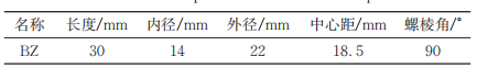
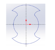
Figure 1 Theoretical End Face Curve
1.1.2 Screw Geometric Model Drawing
In Solidworks software, draw the geometric model of the counter-rotating twin-screw, with the Z-axis positive direction as the polylactic acid extrusion direction. The screw length is 30 mm, and the gap is 0.5 mm. The left screw rotates counterclockwise, and the right screw rotates clockwise. Draw the left and right screws as shown in Figure 2.
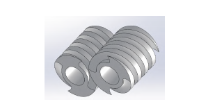
Figure 2 Three-dimensional model of the screw element (BZ)
Based on this, grooves are opened around the screw at 120°, 90°, and 60° respectively, with 3, 4, and 6 grooves, each with a width and depth of 1 mm. The grooves are rounded at the corners to prevent PLA from accumulating at these points. The original component of the grooved screw is shown in Figure 3.
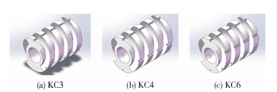
Figure 3: Three-dimensional model of the screw element
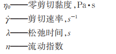
Based on Table 2, draw the three-dimensional model of the flow channel as shown in Figure 4.
Table 2 Channel Component Modeling Parameters
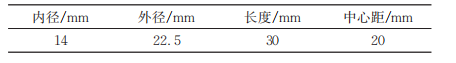
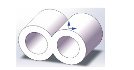
Figure 4 Three-dimensional model of the flow passage component
1.2
Establish a mathematical model for the extrusion process.
1.2.1 Basic Assumptions
Before conducting simulation analysis, make the following assumptions based on the actual situation and the characteristics of polylactic acid material:
The melt is fully filled in the runner and is incompressible.
The extrusion environment is a thermally stable flow field at 190 °C.
The flow state is laminar flow with a small Reynolds number.
Inertial forces, gravitational forces, etc. are neglected.
(5) Characteristics of polylactic acid: relaxation time is 0.0607 s, shear viscosity is 2504.235 Pa·s, and fluid index is 0.253.
1.2.2 Basic Equations
The molten flow of polylactic acid must satisfy the three fundamental fluid mechanics equations: the mass conservation equation, the energy conservation equation, and the momentum conservation equation. The previous assumption is that the extrusion takes place in an isothermal environment at 190 °C, so it is only necessary to solve the mass conservation equation and the momentum conservation equation. In fluid mechanics, mass conservation can be viewed as the material balance in a small cubic unit in Cartesian coordinates. Based on the above situation, the fundamental equation is:
Conservation of mass equation:
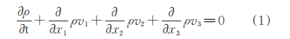
In dealing with fluids that include polymer melts, it is generally assumed that these materials are incompressible, meaning that the density ρ is constant, allowing the above equation to be simplified.

Momentum conservation equation (equation of motion):

Select the Bird-Careau constitutive equation for numerical simulation to explore the relationship between shear rate and viscosity of polylactic acid.

1.3
Establishment of finite element model
1.3.1 Grid Division
The screw and flow channel were meshed using Gambit software. The screw component is relatively complex, and tetrahedral meshing was used; the flow channel component was directly meshed using hexahedral structured mesh. The results are shown in Figure 5.
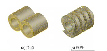
Figure 5 Finite Element Meshing Model of Screw Element and Flow Channel
1.3.2 Setting the Boundary Conditions of the Flow Channel
Polylactic acid flows freely at both the inlet and outlet of the channel, so both the tangential and normal forces are zero, that is, f.n=fs=0;
(2) There is no relative tangential velocity between polylactic acid and the inner wall of the flow channel; both the normal velocity and the tangential velocity are 0, then v.n=vs=0;
(3) The left and right inner holes of the barrel are sliding boundaries with no fluid penetration, the normal velocity and tangential force are 0, thus v.n=0,fs=0;
Due to the power law exponent being less than 0.75, it belongs to a strongly non-Newtonian nonlinear problem, so the Picard iteration algorithm is chosen for convergence calculation.
Simulation Result Analysis
02
2.1
Pressure field
The macro pressure field, as one of the important analysis indicators in fluid mechanics, can fully reflect the pressure-building capacity of the screw and the extrusion speed of the material. As shown in Figure 7, both the standard twin-screw and the slotted twin-screw exhibit an increasing pressure along the base direction, reaching a maximum at the outlet of the flow channel. To more intuitively observe the differences in the pressure-building capacity of the slotted screw channel compared to the conventional extruder channel, a pressure reference axis is established along the positive Z-axis, which is the extrusion direction, with reference points taken every 1 cm, as shown in Figure 6. A line graph is plotted to illustrate the relationship between extrusion distance and pressure. Compared to the standard counter-rotating twin-screw extruder, the slotted screw has a certain impact on the pressure-building capacity of the extruder, as shown in Figure 8. Due to the accumulation of material at the slot, a higher pressure is generated when passing through the rolling gap. Thus, the pressure-building capacity of the slotted screw is stronger than that of the standard screw. However, as the number of slots increases, the space within the flow channel enlarges, weakening the accumulation effect of the material, and the pressure-building capacity of the extruder gradually decreases, though it still remains higher than that of the standard screw.

Figure 6 Pressure Reference Axis Diagram
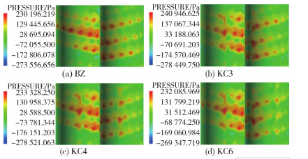
Figure 7 Pressure cloud diagram of four types of screws
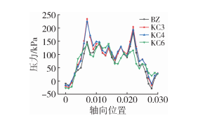
Figure 8 Axial Pressure Line Chart
2.2
Stay time distribution
The commonly used residence time distribution (RTD) is employed to characterize the distribution and mixing ability of materials within the flow channel. RTD is closely related to the formation of extruded fluid quality. The residence time refers to the time taken from when PLA enters the extrusion chamber until it exits the die, which includes the cumulative residence time distribution function and the residence time distribution function. This paper uses the tracer particle trajectory tracking method to study the residence time and mixing ability of the extruder. A certain number of tracer particles (set to 2000 in this paper) are arranged at the flow channel entrance, and the Polyflow's Polystat statistical module is used to calculate and analyze the movement trajectory of tracer particles with the screw rotation in the flow channel. The cumulative residence time distribution curve is shown in Figure 9. There is a certain difference between the residence time curve of the slotted screw and the standard screw. A horizontal reference line is established at the ordinate of 0.8, indicating that the time for 80% of the particles to flow out of the KC6 flow channel is successively greater than KC4, KC3, and BZ. Thus, slotting the screw weakens the extrusion capability of the extruder, causing the material to have a longer residence time in the flow channel, allowing for more thorough longitudinal mixing. It can be seen that the cumulative residence time increases with the number of slots. Figure 10 shows the residence time distribution curve, where the particle residence time is mainly concentrated in the raised portion of the curve. The peak of the BZ curve is the highest, indicating that a larger number of particles have a shorter residence time, which also confirms that slotting leads to a longer extrusion time for the material.
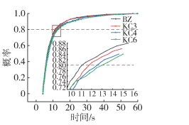
Figure 9 Cumulative Dwell Time Distribution Curve
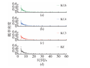
Figure 10 Dwell Time Distribution Curve
2.3
Distribution Mixing Characteristics
2.3.1 Distribution Index
The distribution index is an important indicator for characterizing the distributive mixing performance of a counter-rotating twin-screw extruder. Initially, tracer particles are concentrated at the entry of the flow channel. As the screw rotates, the tracer particles move forward along the screw channel, leading to the uniform mixing of 2000 tracer particles within the flow channel. The homogeneity of the twin-screw extrusion is mainly assessed by the difference between the current distribution of tracer particles and the optimal distribution. The smaller the difference, the better the mixing performance of the extruder and the more uniform the particle distribution. Conversely, the larger the difference, the poorer the mixing performance and distribution uniformity.
In order to ensure that the number of tracer particles remains constant, the simulation conditions for the residence time distribution are modified using the Polydata preprocessing module. The motion trajectories of the tracer particles are analyzed with the Polystat statistical module. The screw rotation angle is recorded in increments of 12° per turn, documenting the process of the screw rotating for one full revolution, resulting in the acquisition of the transient distribution and optimal distribution of the tracer particles.
At the same time, based on the transient distribution and the optimal distribution of the above-mentioned tracer particles, the distribution index is defined according to equation (5).

Where f(l) is the transient distribution function and fopt is the optimal distribution function.
The statistical results of the distribution index for the slotted screw and the conventional screw are illustrated in Figure 11. The distribution index curve of the slotted screw is generally consistent with that of the conventional screw. The peak observed at time zero is due to the reflux phenomenon at the inlet of the extruder. Initially, the particles are unevenly mixed in the extruder, leading to an upward trend in the curve during the time series of 20 to 30. As time progresses, the particle distribution gradually becomes more uniform, and the curve shows a downward trend. The minimum values reached by KC3 and KC6 are similar, but overall, the transient distribution of KC3 is closer to the optimal distribution compared to the other three types of screws, indicating that KC3 has the best mixing uniformity.
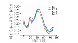
Figure 11 Distribution Index Curve
In Polystat, dynamically display tracer particles, with red and blue tracer particles placed at the entrance, as shown in Figure 12.
Table 3 Distribution of Tracer Particles in Each Screw
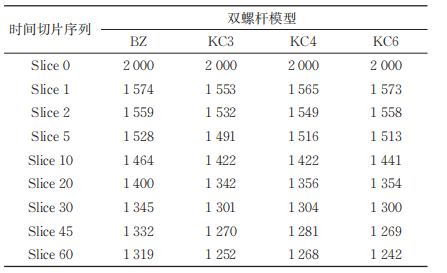
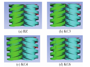
Figure 12: Tracer Particle Mixing Diagram
2.3.2 Separation Scale
The segregation scale is a physical quantity that characterizes the performance of distribution mixing and is also a measure of the average size of regions with the same component in the material. The scale decreases with the increase in the degree of dispersive mixing and distributive mixing, and changes in scale can reflect the degree of material mixing. Therefore, the controlling equations for the segregation scale are shown in equations (6) and (7).
S is the separation scale; cj′ is the concentration at the position; c is the average distribution density; M is the number of relative points; δc^2 is the variance of the particle concentration distribution.
Figure 13 shows the separation scale curves of four types of screws. At the initial moment, the tracer particles are located on both sides of the inlet slice, resulting in a high value; as the mixing action of the screw causes the particles to disperse, the curve declines, indicating a reduction in separation scale. Subsequently, due to the converging action of the screw, the particles aggregate again, causing the curve to rise, with a rapid decrease in separation scale observed in the 10-50 slice. During standard screw extrusion, most particles are present in the C-shaped chamber, while the slotting leads to more irregular motion of particles, resulting in the lowest curve value for KC6, indicating its best axial mixing performance. The separation scale curves of BZ, KC3, and KC4 are similar. After the 50 slice, the separation scale curve rises, indicating that all four types of screws exhibit a backflow phenomenon.
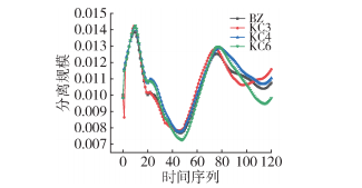
Figure 13 Separation Scale Curve
Experimental Results and Verification Analysis
03
3.1
Main ingredients
PLA, 4032D, Nature Works Company, USA.
3.2
Main Equipment and Instruments
Twin-screw extruder, DT20/44, Nanjing Dingtian Machinery Manufacturing Co., Ltd.; Small vertical injection molding machine, ThermoScientific, USA; Universal material testing machine, CMT6101, Shenzhen New SANS Co., Ltd.
3.3
Sample preparation
Conduct extrusion experiments using a counter-rotating twin-screw extruder with experimental material (PLA). Place the PLA in an electric heating blast drying oven at 80°C for 12 hours. Set the temperature of the melting zone of the twin-screw extruder to 190°C, with a feeding speed of 5 rpm and a screw speed of 60 rpm. After extrusion, pelletize and crush the material, then injection mold it into standard tensile and impact test specimens. Analyze the experimental data and compare the effects of standard screw and slotted screw on the mechanical properties of the extruded material.
3.4
Performance Testing and Structural Characterization
The tensile test is conducted according to GB/T 1040.2-2006; the impact test is conducted according to GB/T 1843-2008.
3.5
Experimental Results Analysis
Due to the grooving of the screw, the pressure-building capacity of the extruder is improved, the degree of irregular particle movement is enhanced, and the axial mixing performance is better. From the experimental results shown in Figures 14-15, it can be observed that the extrusion effect of polylactic acid in the grooved screw is superior to that in the standard screw. Among them, KC3 exhibits the best performance, while KC6 is slightly lower than that of KC3.
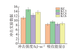
Figure 14 Impact Test Data Graph
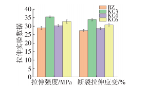
Figure 15 Tensile Test Data Chart
04
Compared to the other three groups, KC3 has better pressure-building capability, allowing materials to be fully compressed and distributed evenly, but it has poorer self-cleaning ability.
The residence time increases with the number of slots, and KC6 is greater than the other three screw groups, exhibiting the best axial mixing performance.
The simulation conditions of this experiment are isothermal, but in practical situations, achieving this is somewhat challenging. Therefore, the temperature can be appropriately controlled according to actual conditions, and the model can be optimized based on the simulation analysis results to select a suitable screw for quantitative production.
【Copyright and Disclaimer】The above information is collected and organized by PlastMatch. The copyright belongs to the original author. This article is reprinted for the purpose of providing more information, and it does not imply that PlastMatch endorses the views expressed in the article or guarantees its accuracy. If there are any errors in the source attribution or if your legitimate rights have been infringed, please contact us, and we will promptly correct or remove the content. If other media, websites, or individuals use the aforementioned content, they must clearly indicate the original source and origin of the work and assume legal responsibility on their own.
Most Popular
-

Key Players: The 10 Most Critical Publicly Listed Companies in Solid-State Battery Raw Materials
-

Vioneo Abandons €1.5 Billion Antwerp Project, First Commercial Green Polyolefin Plant Relocates to China
-

EU Changes ELV Regulation Again: Recycled Plastic Content Dispute and Exclusion of Bio-Based Plastics
-

Clariant's CATOFIN™ Catalyst and CLARITY™ Platform Drive Dual-Engine Performance
-

List Released! Mexico Announces 50% Tariff On 1,371 China Product Categories