


Boost Output by 30%! Solving the Key Pain Points in Polyolefin Modification: Difficult Feeding with High Fillers, Glass Fibers Breaking into Fragments, and Violent Vent Port Blowout
In the modified plastics industry, those working on reinforcement and filling modification of polyolefins are probably spending every day going head-to-head with all kinds of tough performance requirements from downstream customers.The flexural modulus and tensile strength need to be maximized, the heat deflection temperature (HDT) must be high enough, and the surface should be free of floating fibers and defects.The biggest bottleneck is—Costs still need to be reduced further and further!
There’s no way around it: to boost performance and control costs, more and more fibers and mineral fillers have to be added to the formulation.
As long as the high filling starts up, the three major "scenes" on the production line can be quite a headache.
Feed inlet “burping”:Talc powder, being a material with a low bulk density, is too light and airy, causing the screw to slip wildly, and the output cannot be increased no matter what.
Fiberglass “shattered to pieces”:Right out of the die, we found that the high-performance long glass fibers had all been chopped into “stubby scraps,” causing the mechanical properties to tank.
Vacuum Eye “Blowing Bubbles”The vent hole was spewing material like a small volcano. After condensing and sticking to the wall, it baked into black specks and fell back into the material, causing the customer to reject the entire batch.
Today, let’s skip the empty theory and get straight to some practical, shop-floor-ready hard-core insights on how to optimize the compounding process with a co-rotating twin-screw extruder and tackle these three maddening pain points all at once!
In polyolefin modification, calcium carbonate, kaolin, mica, and talc are all familiar regulars. But how to efficiently “feed” them into the screw involves quite a bit of know-how.
Many factories, in order to save trouble, tend to add all fillers together with the plastic pellets from the main feed port at the very front (commonly referred to as “upstream feeding”).
Seasoned process expert, take note:Never do this with high fill formulations!
First, mineral particles mostly have a "grinding" property, which can cause significant wear on the screw and barrel from start to finish. Secondly, low bulk density fillers can easily cause fluidization at the main feeding inlet, leading to slippage and flow restrictions in the equipment.
Worse still, at high loading levels, the unmelted filler easily clumps together in the screw kneading zone, forming hard “pure filler agglomerates” that cannot be broken up no matter how much mixing follows.
Smart people’s positioning:Segmented downstream feeding + smooth exhaust
The truly ingenious combination of techniques is:Let the resin melt through at the front end, and introduce the filler in batches from the downstream feed inlet!
Reference to a very classic barrel combination scheme in the industry.
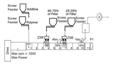
Figure 1 Classic segment and side feeding arrangement of high-filled mineral filler machine cylinder.
Front section (Barrels 1–3):The matrix resin and some additives are pre-melted.
Middle section (Barrel 4):The first side feeder enters the site and takes care of the bulk of the filler.
Connecting section (cylinder 6):Immediately open a vent for atmospheric pressure! This step is absolutely crucial because the low-density packing is filled with air, and it is essential to release the gas here; otherwise, the gas will rebound, and the side feeding outlet will immediately “explode the silo.”
Rear section (barrel 7):The second side feeder is put into operation to replenish the remaining filler.
As for the screw elements, one must respond accordingly based on the filler’s diameter-to-length ratio (Aspect Ratio):
Low aspect-ratio fillers (1–10), such as ground calcium carbonate and kaolin:This type of filler mainly serves to increase rigidity and provide "filler extension." Aggressive screw design is required; it is recommended to use relatively wide kneading block elements (such as 1.5 D length) for strong shearing after side feeding, in order to thoroughly break up agglomerates.
High aspect ratio fillers (greater than 10, such as reinforced talc and mica):These types of fillers can bring tangible reinforcement and improve the HDT effect. To avoid damaging their flake-like or needle-like structures, they must be handled with care, using narrow kneading blocks (such as 0.5D in length) or special elements with a gradual taper and thin-tip design, and performing gentle compounding under low shear.
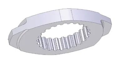
Figure 2 Structure of a Narrow-Disc, Thick-Root Kneading Block for High-Aspect-Ratio Fillers
If the process has been optimized to the limit and the output is still stuck at feeding, then it’s time to rely on the black technology FET (Feeding Enhancement Technology).
A porous permeable microporous plate is embedded in the barrel wall of the feed section, and vacuum is applied while feeding.
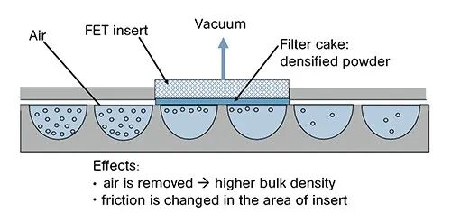
Figure 3 FET Feeding Enhancement Technology Principle (Porous Cylinder Vacuum Adsorption)
The fine filler particles will obediently “adhere” to the barrel wall, forming a dense coating. This coating not only greatly increases the friction between the material and the barrel, completely solving slippage and flow-restriction problems, but also compresses the powder in the process.
Direct effects:Conveying efficiency has skyrocketed, and the production line can finally run at the equipment’s torque limit!
Hidden Dividend:With the same equipment, as output increases, the energy consumption per ton (specific energy consumption) decreases accordingly. With lower energy consumption, the material undergoes less thermal history, resulting in a lower melt temperature, which in turn reduces both thermal degradation of the material and unnecessary consumption of antioxidants—saving money to the core!
For process engineers working with glass fiber- (or carbon fiber-) reinforced polyolefins, there is only one ultimate KPI:Village head!
As long as the effective length of the glass fibers in the resin can be maintained, the rigidity and toughness of the modified material can be maximized. Many people have a misconception that glass fibers are all forcibly broken by the screw’s shear blocks.
The invisible killer behind fiberglass breakage is actually High-concentration "involution"!Research indicates that the large-scale breakage of fiberglass is largely due to the mutual collision and high-frequency friction between fibers.
Here’s an interesting physical phenomenon: when adding 30 wt% glass fiber, the volume fraction in PP (which has a lower matrix density) is significantly lower than in nylon 66 (which has a higher matrix density). So in PP, the glass fibers are less crowded, the collision probability is lower, and as a result, the retained glass fiber length is actually longer!
Screw configuration upgrade: say goodbye to high shear and switch to ZME elements!
To minimize internal damage to the glass fiber, downstream side feeding is an absolute baseline requirement. As soon as the glass fiber is introduced, the resin must immediately wet it out; if the melt does not promptly encapsulate and lubricate it, the dry fibers will rub against one another and shatter into fragments almost instantly.
In the selection of mixing elements, the traditional toothed mixing element (TME), although effective in maintaining residence time, is not fully self-cleaning along the entire line, which can easily create dead zones that cause material buildup on the barrel wall and degradation.
Currently, the industry is more in favor of the new ZME special components.
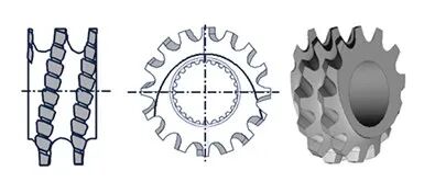
Figure 4 Structure of ZME Low-Shear Long-Term Mixing Element
The structure is impressive.Its overall movement is forward conveying, while the base adopts a reverse conveying design, but the helical ridge is neatly cut with a full circle of forward-oriented tooth grooves.
Perfectly balancedThis structure enables exceptionally strong yet ultra-gentle distributed mixing at extremely low shear stress! In addition, except for the tooth root area, it supports self-wiping throughout, leaving no chance for material buildup or wall scorching. Moreover, its reduced radial dimensions leave a larger clearance for melt flow, greatly reducing mechanical stress on glass fibers.
Measured performance:Experimental data have confirmed that, in the glass-fiber-reinforced polyolefin process, introducing ZME elements can achieve perfect disintegration and wetting of the glass fibers with lower energy input, resulting in fibers that are long and beautiful, and mechanical properties that are maximized!
Speaking of vacuum venting holes, they are simply a nightmare shared by operators and quality control managers alike. Traditional vented barrels with top openings have two fatal drawbacks that are impossible to avoid.
Frequent material leakage.Especially when low-viscosity melt or high-volatility gas overflows, the melt can easily be expelled together with the gas, not only polluting the environment but also forcing workers to stop the machine at any time and clean it up with shovels in hand.
2. Finished product black spot outbreak:Even without large-scale material carryover, volatiles readily condense on the vertical walls of the vacuum chamber. Exposed to high temperatures of several hundred degrees for long periods, these deposits gradually carbonize and char. Over time, once the black coke-like chunks loosen and fall back into the main melt flow channel, all the resulting pellets will contain black specks and be scrapped outright.
Since the top is prone to chipping and material overflow, the smartest solution in terms of process is to move the vent hole to the side!
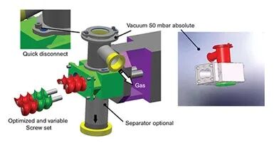
Figure 5 Structure of the ZS-EG Side-Feed Twin-Screw Degassing System
Using a lateral twin-screw degassing device, its logic is very straightforward.
Physical obstruction of black spots:Because the connection is on the side of the main unit, even if carbonized condensate flakes off inside the vacuum hood or piping, it will only fall downward under gravity and can never “accurately drop back into” the main chamber, thereby eliminating the contamination pathway of black specks at the source.
Powerful back-push, smooth gas release.Inside the side degassing unit, two small intermeshing, counter-rotating screws are installed. Gas and water vapor can be freely drawn off by vacuum through the screw grooves with axial openings; but once the melt tries to escape as well, the intermeshing screws exert a powerful reverse push, forcibly driving the material back into the main flow channel inside the primary barrel.
With the side degassing system in place, operators no longer have to stand guard at the vent with a shovel. By completely eliminating the risk of material spewing out, the entire compounding line can be pushed to full throttle and accelerated aggressively. While improving the overall appearance quality of the product, the line’s total output can typically jump by 20%–30%!
How can you choose in a way that truly hits the mark?
In the first half of the competition in the modified plastics industry, the key factor is whose…"Exquisite formula"In the second half, what matters is whose determination prevails.Craftsmanship brought to a more extreme level。
In the face of the development trend of highly filled and high-performance polyolefins, only by making good use of advanced process equipment such as segmented downstream side feeding, FET feeding enhancement, ZME gentle and long elements, and lateral twin-screw degassing, can production lines break through their original limits and truly achieve a dual-dimensional breakthrough in both efficiency and capacity while maintaining high quality!
【Copyright and Disclaimer】The above information is collected and organized by PlastMatch. The copyright belongs to the original author. This article is reprinted for the purpose of providing more information, and it does not imply that PlastMatch endorses the views expressed in the article or guarantees its accuracy. If there are any errors in the source attribution or if your legitimate rights have been infringed, please contact us, and we will promptly correct or remove the content. If other media, websites, or individuals use the aforementioned content, they must clearly indicate the original source and origin of the work and assume legal responsibility on their own.
Most Popular
-

Raw Material Supply Shortage! INEOS Phenol Declares Force Majeure on Phenol and Acetone Businesses
-

Lantiche Group To Shut Down Italian Adipic Acid Production Plant
-

Resin Market Trends Diverge: Buyers' Bargaining Advantage Hit by Geopolitical Uncertainty
-

AI Computing Power Demand Ignites Electronic Fabrics! China Jushi Hits Limit Up! Domestic Substitution Welcomes Golden Window
-

Strait of Hormuz Blocked Again, Supply-Demand Mismatch in Polyolefin Market Set to Intensify!